heatilator fireplace manual

Heatilator Fireplace Manual: A Comprehensive Guide

Ventoy, a versatile open-source tool, simplifies creating bootable USB drives for various ISO, WIM, IMG, and EFI files. It eliminates repetitive formatting, allowing direct booting from copied image files, supporting diverse operating systems like Windows and Linux.

Heatilator models, including older styles, benefit from understanding their specific features and maintenance, as detailed in comprehensive guides and readily available resources.

Understanding Heatilator Fireplace Models

Heatilator fireplaces encompass a diverse range of models, each designed with unique features and functionalities. Recognizing these distinctions is crucial for proper operation, maintenance, and troubleshooting. Early Heatilator designs, often referred to as “old-style,” differ significantly from contemporary models in terms of combustion systems and venting requirements.

Modern Heatilator fireplaces frequently incorporate advanced technologies like direct-vent gas fireplaces, offering enhanced efficiency and safety. These models utilize sealed combustion, drawing air directly from outside, minimizing indoor air depletion. Conversely, older models may rely on natural convection and require a dedicated air supply.

Ventoy, while not directly related to fireplace models, exemplifies a user-friendly approach to managing multiple systems – akin to understanding the variety within the Heatilator lineup. Identifying your specific model number is paramount, as it unlocks access to the correct manual and parts diagrams. Different models necessitate different maintenance procedures and fuel recommendations. Understanding these nuances ensures optimal performance and longevity of your Heatilator fireplace.

Identifying Your Specific Heatilator Model Number

Locating your Heatilator fireplace’s model number is the first step towards accessing accurate information for operation and repair. This unique identifier unlocks access to the correct manual, parts lists, and troubleshooting guides. The model number is typically found on a label affixed to the fireplace itself, often within the firebox, on the side, or near the gas valve.

Carefully inspect these areas, using a flashlight if necessary. The label may be a silver or white sticker containing a series of letters and numbers. Record this number precisely, as even a single incorrect digit can lead to inaccurate information. Like utilizing Ventoy to pinpoint the correct ISO, the model number is key.

If the label is missing or illegible, consult your original purchase documentation or contact Heatilator customer support. Providing details like the fireplace’s age, size, and features can assist them in identifying the model. Having the correct model number streamlines maintenance, ensures compatible replacement parts, and guarantees safe operation of your Heatilator fireplace.

Safety Precautions and Warnings

Heatilator fireplaces, while providing warmth and ambiance, require strict adherence to safety precautions. Ventoy simplifies bootable media, but fireplaces demand constant vigilance. Never leave a burning fireplace unattended, and always ensure a functional carbon monoxide detector is installed nearby. Keep flammable materials – furniture, curtains, paper – a safe distance from the fireplace.

Regularly inspect the chimney and vent system for obstructions or damage, ensuring proper ventilation. Children and pets should be supervised closely around the fireplace, and educated about the dangers of hot surfaces. Do not use flammable liquids to start or accelerate a fire.

If you smell gas, immediately shut off the gas supply and contact a qualified technician. Improper installation or modification can create hazardous conditions. Always follow the manufacturer’s instructions outlined in this manual, and heed all warning labels. Prioritizing safety ensures a pleasurable and secure fireplace experience.

Installation Guidelines for Heatilator Fireplaces

Heatilator fireplace installation demands meticulous attention to detail and adherence to local building codes. Similar to preparing a Ventoy drive, a solid foundation is crucial. Professional installation is strongly recommended, ensuring proper sizing and clearances from combustible materials. The fireplace must be installed on a structurally sound surface capable of supporting its weight.

Chimney and vent system installation are paramount, requiring correct sizing and materials to ensure safe and efficient operation. Gas line connections must be performed by a qualified technician, verifying leak-free connections. Electrical connections, if applicable, should comply with national and local electrical codes.

Carefully follow the manufacturer’s instructions regarding hearth extensions and required clearances. Proper sealing around the fireplace unit prevents drafts and ensures optimal performance. A thorough inspection post-installation verifies all connections and components are secure and functioning correctly.

Operating Instructions: Starting and Maintaining a Fire

Heatilator fireplaces, like preparing a bootable drive with Ventoy, require a specific sequence for optimal performance. Before initiating, ensure the damper is fully open and the area around the fireplace is clear of combustible materials. For gas fireplaces, follow the lighting instructions detailed in your model’s manual – typically involving turning the gas supply on and igniting the pilot light.

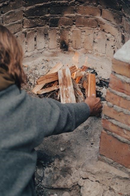
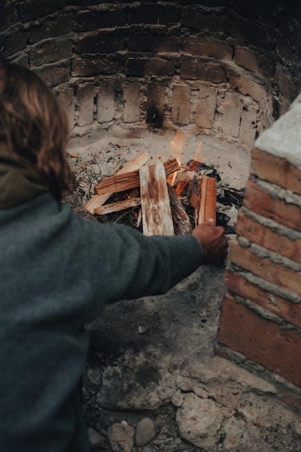
When building a wood fire, start with kindling and gradually add larger pieces of wood, ensuring adequate airflow. Avoid overloading the firebox, as this can restrict oxygen flow and create excessive smoke. Monitor the fire regularly, adding wood as needed to maintain a consistent flame.

To maintain a healthy fire, periodically adjust the logs for optimal burning. Never leave a fire unattended, and always ensure it is completely extinguished before leaving the house or going to bed. Utilize a fireplace screen to prevent sparks and embers from escaping.

Fuel Recommendations for Heatilator Fireplaces

Heatilator fireplaces, much like Ventoy’s compatibility with diverse ISO files, accommodate various fuel types, though specific recommendations depend on your model. For wood-burning fireplaces, seasoned hardwood – such as oak, maple, or birch – is ideal, boasting a higher heat output and cleaner burn compared to softwoods.

Wood moisture content is crucial; aim for below 20% to minimize smoke and creosote buildup. Avoid burning green or wet wood, as it produces significantly more pollutants and reduces heating efficiency. For gas fireplaces, natural gas or propane are commonly used, adhering to local gas codes and regulations.

Never burn treated wood, plastics, or other non-approved materials, as these release harmful toxins. Always store fuel properly, keeping wood dry and gas tanks safely secured. Refer to your Heatilator manual for specific fuel guidelines tailored to your fireplace model, ensuring optimal performance and safety.

Ventilation and Chimney Requirements

Similar to how Ventoy requires a compatible USB drive for optimal function, Heatilator fireplaces demand proper ventilation and a correctly installed chimney system for safe and efficient operation. Adequate airflow is paramount, ensuring sufficient combustion air and preventing carbon monoxide buildup. Most models require dedicated fresh air intake systems, particularly in tightly sealed homes.

Chimney requirements vary based on fuel type and local building codes. Wood-burning fireplaces necessitate a masonry or listed stainless-steel chimney, sized appropriately for the fireplace’s flue outlet. Gas fireplaces often utilize vented or vent-free systems, with specific requirements outlined in the installation manual.

Regular chimney inspections are crucial, checking for creosote accumulation, blockages, and structural integrity. Ensure the chimney is properly sealed and maintained to prevent leaks and drafts. Always consult local codes and a qualified professional for chimney installation and maintenance.

Regular Maintenance and Cleaning Procedures

Much like maintaining Ventoy’s USB drive with updated ISO files, Heatilator fireplaces require consistent upkeep for optimal performance and safety. Regular cleaning is essential, removing ash and debris from the firebox after each use, or at least before each burn. Inspect the glass door for soot buildup, cleaning with a fireplace-specific glass cleaner.

Annual inspections by a qualified technician are highly recommended. This includes checking the gas valve, pilot light assembly (if applicable), and venting system for obstructions or damage. Log sets should be inspected for cracks or deterioration, and replaced as needed.

Pay close attention to the air intake vents, ensuring they are free from dust and debris; A clean fireplace operates more efficiently and reduces the risk of malfunctions. Following these procedures extends the lifespan of your Heatilator and ensures a safe, enjoyable heating experience.

Troubleshooting Common Issues

Similar to resolving issues with a Ventoy bootable drive, Heatilator fireplaces can sometimes present challenges. A common problem is a pilot light that won’t stay lit; check the thermocouple and gas supply. Gas valve issues may manifest as inconsistent flames or no ignition – professional inspection is crucial here.

If the fireplace fails to ignite, verify the gas supply is on and the pilot light is functioning. Inspect the log set for proper placement; incorrect positioning can disrupt the flame pattern. Soot buildup can indicate ventilation problems, requiring chimney inspection.

For persistent issues, consult a qualified technician. Attempting complex repairs without expertise can be dangerous. Remember, regular maintenance, like keeping Ventoy updated, prevents many problems. Always prioritize safety and follow the manufacturer’s guidelines.

Pilot Light Problems and Solutions

A frequently encountered issue with Heatilator fireplaces is a pilot light that repeatedly extinguishes. This often stems from a faulty thermocouple, the safety device that senses flame presence. A weak or dirty thermocouple won’t keep the gas valve open, shutting off the pilot. Cleaning the thermocouple with fine steel wool can sometimes resolve this.

Another cause is a restricted gas supply. Ensure the fireplace’s gas valve is fully open and that there are no kinks in the gas line. Air currents can also disrupt the pilot flame; shield it from drafts. If the pilot light ignites but doesn’t stay lit after several attempts, the gas valve itself may be failing.

Ventoy’s reliability mirrors the need for a consistently functioning pilot. If troubleshooting fails, contact a qualified technician. Never attempt to bypass safety features.

Gas Valve Issues

Problems with the gas valve in a Heatilator fireplace can manifest in several ways, often preventing the fireplace from reaching its desired heat output or failing to ignite altogether. A common symptom is a clicking sound when attempting to light the fireplace, but no gas flow. This suggests a faulty solenoid within the valve.

Another issue is a slow or erratic gas flow, leading to a weak flame. This could indicate a partially blocked valve or internal corrosion. Always ensure the gas supply is turned off before inspecting or attempting any repairs on the gas valve. Ventoy’s consistent operation relies on stable power, much like a gas valve needs a consistent gas supply.

If you suspect a gas valve malfunction, it’s crucial to contact a qualified technician for diagnosis and repair. Tampering with gas valves can be extremely dangerous. Replacement is often the safest and most effective solution.

Log Set Maintenance

Maintaining your Heatilator fireplace’s log set is crucial for both aesthetic appeal and safe operation. Over time, soot and dust accumulate on the logs, diminishing their realistic appearance and potentially affecting flame patterns. Regular cleaning, ideally before each heating season, is recommended.

Use a soft brush or vacuum with a brush attachment to gently remove debris. Avoid using abrasive cleaners, as these can damage the log material. Inspect the logs for cracks or damage; replace any compromised pieces immediately. Proper log placement is also vital – ensure they are arranged according to the manufacturer’s instructions to promote efficient combustion.

Like Ventoy needing consistent file integrity for reliable booting, a well-maintained log set ensures consistent and safe fireplace performance. Periodically check the mounting pins or brackets securing the logs, tightening them if necessary. A clean and properly arranged log set enhances the fireplace’s beauty and safety.

Heatilator Fireplace Parts and Replacement

Replacing Heatilator fireplace parts is sometimes necessary for optimal performance and safety. Common components requiring replacement include gas valves, pilot assemblies, thermocouples, and log sets. Identifying the correct part number for your specific model is paramount – consult your owner’s manual or the Heatilator website for assistance.

When sourcing replacement parts, prioritize genuine Heatilator components to ensure compatibility and maintain warranty validity. While aftermarket options exist, they may not meet the same quality standards. Installation should ideally be performed by a qualified technician, especially for gas-related components, to prevent leaks or malfunctions.

Similar to how Ventoy requires compatible ISO files for successful booting, a Heatilator fireplace needs correctly matched parts. Always disconnect the gas supply before attempting any repairs. Proper part replacement restores functionality and ensures the continued safe operation of your fireplace, preserving its heating efficiency and aesthetic appeal.

Understanding Heatilator’s Combustion Air Systems

Heatilator fireplaces rely on efficient combustion air systems for safe and effective operation. These systems provide the oxygen necessary for complete fuel combustion, minimizing carbon monoxide production. Understanding how your specific model’s system functions is crucial for proper maintenance and troubleshooting.

Older Heatilator models often utilize natural convection, drawing air from the room. Newer, high-efficiency units may incorporate dedicated air intakes, sometimes requiring ductwork connected to an external air source. Proper airflow is vital; obstructions can lead to incomplete combustion and potential hazards;

Much like Ventoy needs a stable connection to boot ISO files, a Heatilator fireplace needs a consistent air supply. Regularly inspect air vents and intakes for blockages like dust or debris. Ensure adequate room ventilation, especially in tightly sealed homes. A correctly functioning combustion air system guarantees a warm, inviting fire while prioritizing safety and air quality.

Converting a Heatilator Fireplace to Different Fuel Types (If Applicable)

Converting a Heatilator fireplace to a different fuel type – such as from wood to gas, or vice versa – is a complex undertaking and often not recommended without professional assistance. It involves significant modifications to the fireplace’s components and gas supply, demanding strict adherence to local codes and safety regulations.

Similar to how Ventoy allows booting various operating systems, a fuel conversion requires adapting the entire system. This includes replacing the burner, gas valve, and potentially the venting system. Wood-burning fireplaces are not inherently designed for gas, and gas fireplaces lack the necessary firebox construction for wood.

Attempting a DIY conversion can create hazardous conditions, including gas leaks or carbon monoxide poisoning. Always consult a qualified HVAC technician or Heatilator specialist to assess feasibility and perform the conversion safely and correctly. Ignoring these precautions could void warranties and compromise your home’s safety.

Old-Style Heatilator Fireplace Specifics

Older Heatilator fireplaces, predating modern safety features, require particularly careful attention during maintenance and operation. These models often lack the advanced combustion air systems found in newer units, potentially leading to reduced efficiency and increased risk of smoke spillage. Unlike the versatility of Ventoy, which adapts to multiple ISO files, older fireplaces are less adaptable to modern fuel types.

Inspect the firebox for cracks or deterioration in the refractory bricks. The damper mechanism may also be less reliable, requiring frequent adjustments. Ventilation is crucial; ensure the chimney is clear of obstructions and functioning correctly. Due to their age, parts availability can be limited, necessitating creative sourcing or custom fabrication.

Consulting original manuals, if available, is highly recommended. If a manual is unavailable, seek guidance from a qualified fireplace technician experienced with older Heatilator models. Prioritize safety and consider professional inspection before each heating season.

Resources for Heatilator Manuals and Support

Finding documentation for your Heatilator fireplace is crucial for safe and efficient operation. While a tool like Ventoy simplifies accessing multiple operating systems, locating the correct Heatilator manual requires a focused approach. The official Heatilator website is the primary source, often offering downloadable manuals categorized by model number;

Online forums dedicated to fireplaces and wood stoves can be invaluable. These communities frequently host archived manuals and provide a platform for sharing troubleshooting tips. Retailers specializing in fireplaces may also have access to older manuals or be able to direct you to relevant resources.

If online searches prove unsuccessful, contacting Heatilator’s customer support directly is recommended. Be prepared to provide your fireplace’s model number for efficient assistance. Remember to prioritize official sources and qualified technicians for accurate information and safe operation.

Always verify the manual corresponds to your specific model.

honeywell alarm panel manual

Honeywell Alarm Panel Manual: A Comprehensive Guide

Honeywell offers diverse alarm systems, from Vista hardwired panels to Galaxy Flex solutions, catering to residential and commercial needs with MAXPRO Cloud integration.

Honeywell, formerly known as Ademco, has long been a leading innovator in the security industry, providing reliable and advanced alarm systems for both homes and businesses. Their systems are renowned for their robust construction, extensive feature sets, and seamless integration capabilities. The Vista Series, a cornerstone of Honeywell’s offerings, represents a significant portion of their hardwired control panel solutions.

These systems aren’t just about basic intrusion detection; they’re about creating a comprehensive security ecosystem. Honeywell systems can incorporate wireless sensors, remote access control, and sophisticated communication methods, including AlarmNet communicators utilizing internet and LTE connectivity. Whether you require a simple residential setup or a complex commercial installation, Honeywell provides scalable solutions to meet diverse security requirements.

Understanding the Vista Series

The Honeywell Vista Series, evolving from the original Ademco Vista line, represents a family of hardwired alarm control panels. This series is distinguished by its scalability and adaptability, offering models suitable for both residential and commercial applications. Residential options include the Vista 10SE, 10P, 15P, 20P, and 21IP, while commercial listings encompass the Vista 32, 128, 250, and even 500 series.

A key strength of the Vista Series lies in its hybrid capabilities, allowing integration of both hardwired and wireless devices. This flexibility simplifies installation and upgrades. These panels are designed to work seamlessly with Honeywell’s range of sensors and accessories, providing a complete and customizable security solution. The Vista series has remained a mainstay due to its reliability and extensive feature set.

Residential vs. Commercial Honeywell Panels

Honeywell distinguishes its alarm panels based on application, offering both residential and commercial-grade systems. Residential panels, like the Vista 10 Series (10SE, 10P, 15P, 20P, 21IP), prioritize ease of use and affordability, typically supporting fewer zones and devices. They are ideal for homeowners seeking basic security features.

Commercial panels, such as the Vista 32, 128, 250, and 500 Series, are built for larger, more complex environments. These systems offer expanded capacity, supporting numerous zones, users, and advanced features like access control integration. Commercial listings often require specific certifications and adhere to stricter regulatory standards. The choice depends on the scale and security requirements of the property, ensuring optimal protection.

Vista 10 Series (10SE, 10P, 15P, 20P, 21IP)

The Honeywell Vista 10 Series represents a popular choice for residential security, encompassing models like the 10SE, 10P, 15P, 20P, and 21IP. These hardwired control panels offer a reliable foundation for home security systems. The Vista 10P and 20P are particularly noted for their ability to operate without traditional phone lines when paired with an AlarmNet communicator (internet or LTE).

These panels support a range of sensors and accessories, providing customizable protection. The 21IP model introduces internet protocol connectivity for enhanced remote access and control. They are known for their user-friendly interfaces and straightforward installation, making them suitable for both DIY enthusiasts and professional installers. They provide a balance of features and affordability.

Vista 32, 128, 250 & 500 Series

Honeywell’s Vista 32, 128, 250, and 500 Series represent the commercial-grade offerings within the Vista line. These panels are designed for larger and more complex security needs, supporting a significantly higher number of zones and devices compared to the 10 Series. The Vista 250BPT is a prominent model, often utilized in commercial applications.

These systems are “listed” for commercial use, meaning they meet stricter regulatory requirements. They offer advanced features like expanded user access control and sophisticated programming options. Compatibility with AlarmNet communicators allows for robust remote monitoring and control via internet or LTE connections. The Vista 500 provides the highest capacity and scalability within the series, suitable for extensive security deployments.

Key Features of Honeywell Home Security Systems

Honeywell Home Security Systems boast a range of features designed for comprehensive protection and user convenience. Connected options enable automated system control, enhancing usability and responsiveness. Easy-to-use keypads and key fobs provide intuitive operation for arming, disarming, and managing the system.

Wireless sensors offer flexible installation and expandability, minimizing wiring complexities. Integration with MAXPRO Cloud delivers remote access, monitoring, and control via computers or mobile devices. These systems support custom dashboards with instant notifications, keeping users informed of system status and events. Honeywell prioritizes seamless integration and sophisticated solutions for both homes and businesses.

Wireless Sensors and Accessories

Honeywell offers a comprehensive suite of wireless sensors and accessories to enhance security systems. These include door and window contacts, motion detectors, glass break sensors, and smoke/carbon monoxide detectors, all communicating wirelessly with the control panel. This minimizes installation complexity and allows for flexible placement throughout the property.

Key fobs provide convenient remote control, while sirens and strobes offer audible and visual alerts. Wireless repeaters extend the range of the wireless network, ensuring reliable communication across larger areas. Compatibility with AlarmNet allows for professional monitoring and remote access via mobile apps. These accessories contribute to a fully integrated and customizable security solution.

Honeywell Galaxy Flex Series: An Overview

Honeywell’s Galaxy Flex Series represents a fully integrated intruder and access control security solution, designed for small to medium-sized, Grade 2 security systems. The series, encompassing Galaxy Dimension, Flex, and FLEX panels, prioritizes ease of installation and connectivity to the MAXPRO Cloud platform.

This integration simplifies system control and management, enabling multi-site oversight from any computer or mobile device. Custom dashboards deliver instant notifications, while continuous monitoring ensures the health and status of all connected security systems. The Galaxy Flex Series offers a scalable and flexible solution, ideal for businesses seeking a robust and user-friendly security infrastructure.

Galaxy Dimension, Flex, and FLEX Panels

Galaxy Dimension serves as the foundational panel, offering a comprehensive set of features for standard security applications. Galaxy Flex builds upon this, introducing enhanced scalability and flexibility for more complex installations. The Galaxy FLEX panel represents the latest iteration, boasting streamlined installation processes and improved connectivity options.

All three panels share a common platform, simplifying training and maintenance. They support a wide range of wired and wireless devices, allowing for customized system configurations. Integration with MAXPRO Cloud is a key feature, providing remote access, control, and advanced reporting capabilities. These panels are designed to meet the evolving needs of modern security systems.

MAXPRO Cloud Integration

MAXPRO Cloud dramatically enhances Honeywell security systems by offering centralized management and remote access. This cloud-based platform allows users and authorized dealers to monitor system health, receive instant notifications, and manage multiple sites from any computer or mobile device.

Key benefits include simplified control, custom dashboards displaying critical information, and real-time system status updates. MAXPRO Cloud facilitates efficient troubleshooting and proactive maintenance, minimizing downtime. It seamlessly integrates with Galaxy panels like Dimension, Flex, and FLEX, providing a unified security experience. Secure data transmission and robust cybersecurity measures ensure the integrity of your system.

VISTA-250BPT Commercial Alarm Control Panel

The Honeywell VISTA-250BPT is a robust, commercial-grade alarm control panel designed for medium to large-sized businesses. It supports extensive zoning, offering granular control over security areas. This panel is capable of handling numerous wired and wireless sensors, making it highly scalable for complex security needs.

Its key feature is compatibility with AlarmNet communicators, enabling reliable communication via Internet or LTE, eliminating reliance on traditional phone lines. The VISTA-250BPT provides advanced features like event logging, user access control, and remote arming/disarming. With a list price of $1,152.00, it represents a significant investment in comprehensive commercial security.

VISTA-20P: Installation and Benefits

The Honeywell VISTA-20P is a popular choice for residential and small commercial security systems, prized for its ease of installation and robust features. It’s designed to operate without traditional phone lines when paired with an AlarmNet communicator – utilizing Internet or LTE connectivity for reliable alarm signaling.

Benefits include a user-friendly interface, expandable system capacity, and compatibility with a wide range of Honeywell sensors. Installation is streamlined, making it suitable for both DIY enthusiasts and professional installers. The VISTA-20P offers innovative end-user benefits and provides a secure, connected home or business solution.

AlarmNet Communicators (Internet & LTE)

AlarmNet communicators are integral to modern Honeywell security systems, providing reliable alarm transmission via Internet (IP) and LTE cellular networks. These communicators eliminate the need for traditional phone lines, enhancing security and reducing costs.

Internet communication offers a cost-effective solution, while LTE provides a robust backup in case of internet outages, ensuring continuous monitoring. AlarmNet services include remote arming/disarming, event notifications, and system health monitoring. Pairing a VISTA-20P panel with an AlarmNet communicator delivers a secure and connected security experience, offering peace of mind and advanced control.

Honeywell PRO Series Wireless Alarm Systems

Honeywell’s PRO Series represents a cutting-edge line of fully wireless alarm systems, designed for easy installation and scalability. These systems utilize advanced wireless technology, offering reliable communication and extended range. The PRO Series is ideal for both residential and light commercial applications, providing a flexible and cost-effective security solution.

Featuring encrypted wireless sensors and a user-friendly interface, the PRO Series simplifies security management. Integration with AlarmNet allows for remote access and control via smartphone or computer. Alongside the established VISTA and LYNX systems, the PRO Series expands Honeywell’s offerings, catering to evolving security needs.

LYNX L5210 Systems

Honeywell’s LYNX L5210 systems are a popular choice for completely wireless home security, offering a robust and reliable solution without the need for extensive wiring. These systems are known for their ease of installation and user-friendly operation, making them suitable for both DIY enthusiasts and professional installers.

The LYNX L5210 utilizes a secure wireless protocol, ensuring reliable communication between the control panel and its sensors. Compatibility with AlarmNet provides remote access and control capabilities, allowing users to monitor and manage their security system from anywhere. As Honeywell continues to innovate, the LYNX series remains a viable option alongside newer PRO Series systems.

Alarm Communication Methods: Historical Context

Historically, alarm systems relied heavily on traditional telephone lines for communication, transmitting signals via the Public Switched Telephone Network (PSTN). This “plain old telephone” method was the standard for decades, offering a reliable, albeit somewhat slow, means of alerting monitoring centers to alarm events. However, the decline of landlines presented challenges.

Honeywell, along with the industry, adapted by embracing new technologies like AlarmNet, utilizing Internet and LTE cellular communication. These methods offer faster, more secure, and more reliable signal transmission, bypassing the limitations of traditional phone lines. The evolution reflects a shift towards more resilient and feature-rich alarm communication, enhancing overall system performance and user experience.

Programming Honeywell Alarm Panels

Programming a Honeywell alarm panel involves configuring various settings to customize the system’s functionality. User code management is crucial, allowing administrators to create unique access codes for different users with varying levels of authority. This ensures controlled access and accountability.

Zone programming defines how each sensor or detection device is interpreted by the panel – whether it’s an entry/exit point, motion detector, or fire alarm. Proper zone configuration is vital for accurate alarm reporting and minimizing false alarms. Advanced programming often requires specialized knowledge or professional assistance, ensuring optimal system performance and security.

User Code Management

User code management within a Honeywell alarm system is a critical security feature. Administrators can create multiple unique user codes, each granting specific access levels. Master codes provide full system control, while individual user codes can be restricted to arming/disarming only.

Proper code assignment ensures accountability and prevents unauthorized access. Regularly changing user codes is a best practice to maintain security. The system allows for temporary codes, ideal for service personnel or guests, which expire after a set duration. Careful management of these codes is essential for a robust security posture, protecting against potential breaches and ensuring system integrity.

Zone Programming

Zone programming defines how each sensor input (zone) reacts to alarm events. Honeywell panels allow customization of zone types – instant, delay, or no-entry – dictating the system’s response upon activation. Instant zones trigger an immediate alarm, while delay zones provide a grace period for disarming. No-entry zones signal an alarm if armed, regardless of the system’s state.

Proper zone configuration is vital for minimizing false alarms and ensuring accurate threat detection. Each zone can be named for easy identification (e.g., “Front Door,” “Living Room Window”). Advanced settings include tamper protection and cross-zoning, enhancing system reliability. Careful zone programming is crucial for a tailored and effective security solution.

Troubleshooting Common Issues

Honeywell alarm systems, while reliable, can occasionally encounter issues. Low battery alerts are frequent, indicating the need for sensor or panel battery replacement. False alarms often stem from improperly installed sensors, loose wiring, or environmental factors. Regularly testing sensors and ensuring secure connections can prevent these.

Communication failures, especially with older systems relying on phone lines, can occur. Verify phone line connectivity or explore AlarmNet communicators for internet/LTE backup. If the keypad displays error codes, consult the manual for specific troubleshooting steps. Remember to document any changes made during troubleshooting for future reference and potential technician assistance.

Low Battery Alerts

Low battery alerts on a Honeywell system signal diminished power in wireless sensors or the control panel’s backup battery. These alerts typically appear on the keypad display, often accompanied by a specific zone number indicating the affected sensor. Immediate attention is crucial, as depleted batteries compromise system reliability.

Replace sensor batteries with the correct type (usually AA or AAA). For the control panel, a qualified technician should replace the backup battery, as it involves handling electrical components. Ignoring these alerts can lead to system failure during a power outage. Regularly scheduled battery checks, at least annually, are recommended preventative maintenance.

False Alarm Prevention

False alarms are a common issue with security systems, potentially leading to fines and reduced emergency response. Honeywell systems offer features to minimize these occurrences. Ensure all doors and windows are securely closed before arming the system. Properly adjust sensor sensitivity to avoid triggering from pets or environmental factors like tree branches.

Educate all users on proper arming and disarming procedures, including entry/exit delays. Utilize zone bypass features for areas with known potential triggers (e.g., a window left open). Regularly test the system to confirm functionality and identify potential issues. Consider professional monitoring for faster response and verification before dispatching authorities.

Battery Backup Systems

Honeywell alarm panels incorporate battery backup systems to ensure continued operation during power outages. These batteries, typically sealed lead-acid, provide temporary power to the control panel and connected devices, maintaining security even when AC power is unavailable. Regular testing of the battery backup is crucial – most panels have a self-test function or indicate battery status on the keypad.

Battery lifespan varies depending on usage and environmental conditions, generally lasting 3-5 years. Low battery alerts will be displayed on the keypad, prompting replacement. It’s recommended to replace batteries proactively during scheduled maintenance. Proper battery maintenance guarantees uninterrupted security, safeguarding your property even during extended power disruptions.

Keypad Operation and Functions

Honeywell alarm system keypads serve as the primary interface for user interaction. Common functions include arming and disarming the system in various modes (Away, Stay, Night), entering user codes for access, and responding to alarm events. Keypads often display system status, zone bypass information, and trouble alerts like low battery warnings.

Different keypad models offer varying features, including panic buttons for immediate emergency response and programmable function keys for customized shortcuts. Understanding the specific keypad’s layout and button functions is essential for effective system operation. Refer to your panel’s manual for detailed instructions on navigating the keypad and utilizing its full range of capabilities.

Remote Access and Control

Honeywell alarm systems, particularly when paired with AlarmNet communicators (Internet or LTE), enable remote access and control via smartphone apps or web portals. This allows users to arm or disarm the system, view system status, receive real-time alerts, and manage user codes from anywhere with an internet connection.

Remote access provides enhanced convenience and peace of mind, enabling users to respond to alarms or check system status while away from home or business. MAXPRO Cloud integration further streamlines remote management, offering centralized control and monitoring capabilities. Ensure secure remote access by utilizing strong passwords and enabling two-factor authentication where available.

System Updates and Firmware

Honeywell regularly releases firmware updates for its alarm panels to enhance performance, address security vulnerabilities, and introduce new features. These updates are crucial for maintaining optimal system functionality and protecting against potential threats. Updates are typically applied through the AlarmNet platform or via a direct connection to the panel.

It’s essential to check for and install firmware updates promptly when they become available. MAXPRO Cloud often facilitates streamlined update processes. Before initiating an update, it’s recommended to back up the system configuration to prevent data loss. Following the update instructions carefully ensures a smooth and successful process, keeping your Honeywell system secure and up-to-date.

Honeywell Alarm Panel Manual Resources

Honeywell provides a wealth of resources to assist users with their alarm systems. Official manuals, covering installation, programming, and troubleshooting, are available on the Honeywell Home website and through authorized dealers. These resources detail the specifics of each panel series, including Vista, Galaxy, and LYNX systems.

Additionally, AlarmNet offers online support and documentation. Numerous online forums and communities dedicated to Honeywell security systems provide valuable insights and peer-to-peer assistance. Accessing these resources ensures users can effectively manage and maintain their systems, maximizing their security benefits. Remember to always refer to the official documentation for accurate and up-to-date information.

Finding Specific Manuals Online

Locating the correct Honeywell alarm panel manual online requires knowing your system’s model number. Start with the official Honeywell Home website; their support section often hosts downloadable PDFs for various panels like Vista (10SE, 20P, 32, etc.) and Galaxy series.

Alternatively, utilize search engines with precise terms like “Honeywell Vista-20P manual” or “LYNX L5210 installation guide”. Authorized Honeywell dealers frequently provide links to manuals on their websites. Beware of unofficial sources; prioritize documentation directly from Honeywell or reputable distributors to ensure accuracy and avoid outdated information. AlarmNet’s resources can also be helpful for communicator-specific guides.

Understanding System Zones

Honeywell alarm systems divide your protected area into zones, each representing a specific area or group of sensors. Common zones include entry/exit doors, windows, motion detectors, and internal areas. Proper zone programming is crucial for accurate alarm identification and response.

Each sensor is assigned to a zone during system setup. Vista and Galaxy panels allow for customized zone configurations, including naming zones (e.g., “Front Door,” “Living Room”) and defining their behavior – instant, entry delay, or exit delay. Understanding zone definitions helps pinpoint the source of an alarm event, minimizing false dispatches and ensuring a swift, targeted response. Refer to your panel’s manual for detailed zone programming instructions.

Wiring Diagrams and Schematics

Honeywell alarm panel installation requires careful attention to wiring diagrams and schematics. These visual guides illustrate the correct connections between the control panel, sensors, communicators, and power supplies. Accurate wiring is paramount for system functionality and reliability.

Vista and Galaxy series manuals typically include detailed wiring schematics for various configurations. These diagrams specify wire colors, terminal assignments, and power requirements. When modifying or troubleshooting a system, always consult the relevant schematic. Incorrect wiring can lead to false alarms, system malfunctions, or even damage to the control panel. Professional installation is recommended if you are unfamiliar with electrical wiring practices.

Compliance and Certifications

Honeywell alarm systems undergo rigorous testing and certification to meet industry standards for safety and performance. Residential and commercial panels often carry UL (Underwriters Laboratories) listings, indicating compliance with fire alarm and burglary protection requirements.

Compliance ensures the system functions reliably in emergency situations and minimizes false alarms. Certifications demonstrate adherence to national and local codes. Vista and Galaxy series panels are designed to meet NFPA (National Fire Protection Association) guidelines. Proper installation and adherence to manufacturer’s instructions are crucial for maintaining compliance. Always verify that the installed system meets the specific requirements of your jurisdiction.

Future Trends in Honeywell Security Systems

Honeywell is actively integrating AI and machine learning into its security offerings, enhancing threat detection and reducing false alarms. Expect increased cybersecurity measures to protect against hacking and data breaches, crucial with growing MAXPRO Cloud reliance.

Wireless technology will continue to advance, offering easier installation and greater flexibility. Video verification, combining alarm signals with live footage, is becoming standard. Smart home integration will deepen, allowing seamless control of security, lighting, and appliances. Open architecture systems, compatible with third-party devices, are gaining traction. Remote diagnostics and proactive maintenance will become more prevalent, ensuring optimal system performance.

e-collar technologies et-300 mini educator remote dog training collar manual

E-Collar Technologies ET-300 Mini Educator: A Comprehensive Guide

This guide details the ET-300 Mini Educator‚ a remote training collar․ It covers setup‚ operation‚ and training‚ utilizing the 34-page PDF manual and online resources for effective‚ safe use․

The E-Collar Technologies ET-300 Mini Educator is a highly regarded remote dog training collar‚ known for its compact design and effective range – up to a half-mile․ This guide serves as a comprehensive resource‚ drawing from the official 34-page owner’s manual and readily available online support․ It’s designed for both novice and experienced trainers seeking to enhance their communication with their canine companions․

Understanding the ET-300 requires familiarizing yourself with its features‚ stimulation modes (Momentary‚ Continuous‚ Combo)‚ and supplementary signals like tone and vibration․ Proper utilization‚ guided by the manual‚ ensures safe and humane training practices․ Accessing the downloadable PDF provides detailed specifications and operational instructions‚ maximizing the collar’s potential․

What is an E-Collar and How Does it Work?

An e-collar‚ or electronic collar‚ is a training tool utilizing remote-controlled stimulation to communicate with a dog․ Unlike punitive methods‚ modern e-collars‚ like the ET-300‚ offer varying levels of stimulation – from gentle taps to adjustable intensity – to redirect unwanted behaviors․ The system comprises a remote transmitter and a collar receiver․

The remote sends a signal to the receiver‚ delivering the chosen stimulation․ The ET-300 manual emphasizes starting at the lowest setting and observing the dog’s response․ Proper use focuses on marking desired behaviors and interrupting unwanted ones‚ fostering clearer communication and a stronger bond between dog and owner․ It’s a tool‚ not a quick fix․

Understanding Remote Dog Training

Remote dog training leverages distance and precise timing for effective communication․ The ET-300 Mini Educator facilitates this by allowing trainers to deliver consistent signals – tone‚ vibration‚ or stimulation – regardless of location within the ½ mile range․ This method excels in reinforcing known commands and addressing behaviors occurring outside of direct supervision․

The ET-300 manual stresses the importance of pairing the remote signal with existing commands․ It’s not about punishment‚ but about creating a clear association․ Successful remote training requires patience‚ consistency‚ and a thorough understanding of your dog’s temperament․ Positive reinforcement remains crucial alongside remote correction․

Key Features of the ET-300

The ET-300 boasts a compact design‚ ½ mile range‚ and waterproof construction․ It offers momentary‚ continuous‚ and combo stimulation‚ plus tone and vibration options․

Compact and Lightweight Design

The ET-300 Mini Educator distinguishes itself with a remarkably compact and lightweight design‚ specifically beneficial for smaller dog breeds․ This feature ensures comfortable wear for your canine companion during training sessions‚ minimizing any potential discomfort or distraction․ The receiver unit is engineered to be unobtrusive‚ allowing for natural movement while maximizing effectiveness․

Compared to larger‚ bulkier e-collars‚ the ET-300’s smaller profile is a significant advantage‚ particularly for dogs sensitive to equipment․ This design prioritizes the dog’s well-being without compromising the functionality needed for successful remote training․ The lightweight nature also contributes to extended wear times‚ crucial for consistent training reinforcement․

1/2 Mile Range

The E-Collar Technologies ET-300 Mini Educator boasts an impressive 1/2 mile range‚ providing substantial flexibility during training exercises․ This extended reach allows for effective communication with your dog in various environments‚ including open fields‚ parks‚ and even larger properties․ The reliable signal transmission ensures consistent control‚ even at the maximum range․

This generous range is particularly advantageous for dogs with a tendency to roam or for training recall in expansive areas․ It empowers owners to maintain consistent communication and correction‚ reinforcing desired behaviors from a distance․ The 1/2 mile capability offers peace of mind‚ knowing you can reliably reach your dog when needed․

Waterproof and Durable Construction

The ET-300 Mini Educator is engineered for resilience‚ featuring waterproof and highly durable construction․ This robust design ensures reliable performance in diverse conditions‚ including rain‚ mud‚ and even submersion in water․ The collar receiver is built to withstand the rigors of active dog training‚ providing long-lasting dependability․

Owners can confidently use the ET-300 during water activities or in challenging outdoor environments without concern for damage․ The durable materials protect the internal components‚ extending the lifespan of the device․ This ruggedness makes it an ideal choice for sporting dogs or those who enjoy outdoor adventures with their canine companions․

Components of the ET-300 System

The ET-300 system includes a remote transmitter‚ collar receiver‚ and charging cable with accessories․ These components work together for effective remote dog training․

Remote Transmitter

The remote transmitter is the handheld control unit for the ET-300 system․ It allows the user to send signals to the collar receiver‚ utilizing various stimulation modes like momentary‚ continuous‚ and combo․ The transmitter features easily accessible buttons for selecting stimulation levels and modes‚ ensuring quick and precise control during training sessions․

It’s designed for comfortable grip and intuitive operation․ The transmitter connects wirelessly to the collar receiver‚ offering a reliable range of up to a ½ mile․ Proper charging is essential for optimal performance‚ and the manual details charging procedures․ Understanding the transmitter’s functions is crucial for effective communication with your dog during training․

Collar Receiver

The collar receiver is the component worn by your dog․ It receives signals from the remote transmitter and delivers the selected stimulation․ This unit is compact and lightweight‚ designed for comfortable wear‚ even for smaller breeds․ The receiver offers multiple stimulation options‚ including tone‚ vibration (tapping sensation)‚ and varying levels of static correction․

Its waterproof and durable construction ensures reliability in various weather conditions․ Proper collar fit is vital for both comfort and effective stimulation․ The manual provides detailed instructions on adjusting the collar for a secure‚ yet comfortable fit․ Regular checks of the receiver’s functionality are recommended for optimal performance․

Charging Cable and Accessories

The ET-300 system includes a specialized charging cable designed for both the remote transmitter and the collar receiver․ Utilizing a standard wall adapter (not always included‚ check your package)‚ both units can be fully charged within a few hours․ The manual emphasizes the importance of using the provided cable to avoid damage․

Additional accessories may include extra contact points of varying lengths‚ suitable for different coat types‚ and a collar strap for secure attachment․ Proper care of the charging cable is crucial for longevity․ Always disconnect the cable when not in use and avoid bending or twisting it excessively․

Setting Up Your ET-300

Initial setup involves charging both the remote and receiver‚ then pairing them according to the manual’s instructions․ Proper collar fit is also essential for effective training․

Charging the Remote and Receiver

Before first use‚ and regularly thereafter‚ ensure both the remote transmitter and collar receiver are fully charged․ The ET-300 system utilizes a charging cable‚ typically included with the unit․ Connect the appropriate end to the charging port on each device․

Charging times may vary‚ but generally‚ a full charge takes approximately 2-3 hours․ A solid indicator light usually signifies a complete charge‚ while a flashing light indicates charging is in progress․ Always refer to the official ET-300 manual for specific charging instructions and warnings․ Avoid overcharging‚ as this could potentially damage the battery․ Consistent charging ensures optimal performance during training sessions․

Pairing the Remote and Receiver

Successfully pairing the remote transmitter and collar receiver is crucial for proper functionality․ The ET-300 typically features a straightforward pairing process‚ often initiated by pressing a specific button combination on both devices simultaneously․ Consult the official ET-300 manual for the exact procedure‚ as it may vary slightly depending on the model․

A successful pairing is usually indicated by a visual or auditory cue‚ such as a steady indicator light or a beep․ If pairing fails‚ ensure both devices are sufficiently charged and within close proximity․ Repeat the pairing process carefully‚ following the manual’s instructions precisely․ A stable connection is essential for reliable remote control during training․

Adjusting the Collar Fit

Proper collar fit is paramount for both comfort and effective training․ The ET-300 collar should sit snugly‚ but not tightly‚ against your dog’s neck․ You should be able to comfortably slide two fingers between the collar and your dog’s skin․ Avoid overly loose fits‚ as this can cause inconsistent contact and stimulation․

Ensure the contact points are positioned correctly‚ touching the dog’s skin․ Regularly check the fit‚ especially during active training sessions․ Adjust the collar as needed to maintain consistent contact․ A secure‚ comfortable fit maximizes training effectiveness and minimizes discomfort for your canine companion․

Understanding Stimulation Modes

The ET-300 offers Momentary‚ Continuous‚ and Combo modes‚ alongside Tapping Sensation (vibration) and Tone Stimulation‚ providing versatile training options for diverse dog temperaments․

Momentary Stimulation

Momentary Stimulation‚ a key feature of the ET-300‚ delivers a brief‚ controlled pulse of stimulation when the user presses and holds the activation button on the remote transmitter․ This mode is ideal for precise timing and clear communication with your dog during training sessions․

It allows for immediate correction of unwanted behaviors‚ as the stimulation stops the instant the button is released․ The duration of the stimulation is entirely controlled by the trainer‚ enabling customized adjustments based on the dog’s sensitivity and responsiveness․

This mode is particularly effective for marking desired behaviors or interrupting undesirable actions‚ offering a clear signal without prolonged discomfort․ Proper use requires careful observation of the dog’s reaction to ensure effective communication and avoid over-correction․

Continuous Stimulation

Continuous Stimulation‚ offered by the ET-300‚ provides a constant level of stimulation as long as the activation button on the remote transmitter is held down․ This mode is best utilized when a dog requires sustained pressure to understand a command or cease an unwanted behavior․

Unlike momentary stimulation‚ it doesn’t require constant button presses for continued effect․ However‚ responsible use is crucial; release the button immediately when the dog responds to avoid unnecessary discomfort․

It’s important to start with the lowest possible setting and gradually increase it until a noticeable response is observed‚ always prioritizing the dog’s well-being and avoiding over-correction․ Careful monitoring of the dog’s reaction is essential for effective training․

Combo Mode (Momentary + Continuous)

The ET-300’s Combo Mode uniquely blends momentary and continuous stimulation‚ offering a versatile training tool․ When activated‚ a brief‚ sharp pulse (momentary) is immediately followed by a sustained stimulation (continuous) as long as the button is held․

This combination can be particularly effective for dogs needing a stronger initial signal to grab their attention‚ followed by consistent pressure to reinforce the desired behavior․ It’s ideal for situations requiring both immediate correction and sustained guidance․

As with all modes‚ begin at the lowest setting and carefully observe your dog’s response‚ adjusting as needed․ Responsible use and avoiding over-correction are paramount for a positive training experience․

Using the ET-300 for Training

Effective training utilizes tone‚ vibration‚ and low-level stimulation․ The ET-300 supports these methods‚ alongside momentary and continuous options‚ for optimal dog training results․

Tone Stimulation

The ET-300’s tone stimulation feature offers a distinct auditory cue for your dog․ This function serves as a communication tool‚ allowing you to signal your dog remotely without employing any physical sensation․ It’s particularly useful for reinforcing previously learned commands or capturing your dog’s attention from a distance․

Many trainers recommend introducing the tone before utilizing any level of electrical stimulation․ Pair the tone with positive reinforcement – praise and rewards – when your dog responds appropriately․ This establishes a positive association with the sound․ The tone can be used as a ‘check-in’ signal‚ prompting your dog to look towards you‚ or as a marker for desired behaviors․ Experiment with the tone’s duration and frequency to find what works best for your individual dog․

Tapping Sensation (Vibration)

The ET-300 Mini Educator incorporates a tapping sensation‚ often described as a vibration‚ similar to that of a cell phone․ This feature provides a subtle‚ non-electrical form of communication with your dog․ It’s an excellent option for dogs sensitive to stimulation or as a preliminary step before introducing higher levels․

The vibration can be used to redirect your dog’s attention‚ interrupt unwanted behaviors‚ or reinforce known commands․ Like the tone‚ it’s best introduced with positive reinforcement․ Pair the tapping sensation with praise and rewards when your dog responds correctly․ Adjust the intensity level to find what effectively gets your dog’s attention without causing discomfort or anxiety․

Low-Level Stimulation for Awareness

The ET-300’s lowest stimulation levels are designed to simply gain your dog’s attention‚ not to deliver correction․ Think of it as a gentle “tap” – a sensation they notice‚ prompting them to look towards you․ This is crucial for establishing communication and building a foundation for more complex training․

Begin training by finding the level your dog just recognizes․ Observe for subtle cues like an ear twitch or head turn․ Avoid levels causing any visible reaction like flinching or vocalization․ Use this low-level stimulation alongside verbal cues and positive reinforcement to create a positive association with the collar and your commands․

Safety Precautions and Best Practices

Always start at the lowest stimulation level and carefully observe your dog’s reaction․ Avoid over-correction‚ prioritizing positive reinforcement for optimal training results․

Starting with the Lowest Stimulation Level

It is crucial to begin training with the ET-300 on its lowest possible stimulation setting․ This ensures you identify the minimal level your dog responds to‚ avoiding unnecessary discomfort or fear․ The goal isn’t to punish‚ but to communicate effectively․ Gradually increase the level‚ one increment at a time‚ only if your dog doesn’t acknowledge the current setting․

Pay close attention to your dog’s body language․ Subtle cues like an ear twitch‚ head turn‚ or slight change in pace indicate they’ve felt the stimulation․ Once you observe a response‚ that’s your working level․ Remember‚ consistency and clear communication are key to successful and humane remote training․ Always prioritize positive reinforcement alongside the e-collar․

Observing Your Dog’s Response

Carefully monitor your dog’s reaction to each stimulation level with the ET-300․ Look for subtle indicators – a head turn‚ ear flick‚ change in posture‚ or a momentary pause in their current activity․ These signals demonstrate they’ve perceived the stimulation․ Avoid increasing the level if any response is observed; that’s your dog’s recognition point․

Ignoring these cues and continuing to escalate can cause anxiety or fear․ A correct response isn’t about causing discomfort‚ but about clear communication․ Positive reinforcement immediately following a correct response solidifies the desired behavior․ Consistent observation ensures a safe and effective training experience with the Mini Educator․

Avoiding Over-Correction

Over-correction with the ET-300 can damage your relationship with your dog and hinder training progress․ Remember‚ the goal isn’t punishment‚ but clear communication․ Utilize the lowest possible stimulation level that elicits a response‚ and avoid prolonged or repeated stimulation․ Focus on marking the desired behavior immediately with praise and rewards․

If your dog shows signs of stress – tucked tail‚ flattened ears‚ excessive panting – reduce the stimulation level or end the session․ Consistent‚ gentle guidance is far more effective than harsh corrections․ Prioritize positive reinforcement and build a trusting bond with your canine companion․

Troubleshooting Common Issues

Common problems include connection failures‚ unresponsive collars‚ and battery concerns․ Refer to the manual for solutions‚ ensuring proper charging and pairing procedures are followed․

Remote Not Connecting to Receiver

If the remote fails to connect to the receiver‚ first ensure both units are adequately charged‚ as low battery levels can hinder pairing․ Consult the ET-300 manual for specific pairing instructions; typically‚ this involves a sequence of button presses on both devices․

Verify that the remote and receiver are within range during the pairing process․ Interference from other electronic devices could also disrupt the connection․ Try re-pairing in a different location․ If issues persist‚ a reset of both the remote and receiver – as detailed in the manual – might be necessary․

Contact E-Collar Technologies support if the problem continues‚ providing your device’s serial number for assistance․

Collar Not Responding

If the collar receiver isn’t responding‚ begin by confirming the unit is powered on and adequately charged․ A depleted battery is a common cause․ Ensure the remote is properly paired with the receiver‚ referencing the ET-300 manual’s pairing instructions if needed․

Check the contact points on the collar against your dog’s skin; they must make firm contact for stimulation to be delivered․ Clean the contact points to remove any dirt or debris․ Verify the stimulation level isn’t set to zero․

If the issue persists‚ try resetting the receiver as outlined in the manual․ Contact E-Collar Technologies support for further troubleshooting․

Battery Life Concerns

The ET-300’s battery life depends on usage frequency and stimulation levels․ Higher levels and frequent use will naturally deplete the battery faster․ Ensure both the remote and receiver are fully charged before each training session․ Avoid leaving the units in extreme temperatures‚ as this can impact battery performance․

To maximize battery life‚ turn off the remote when not in use․ The manual details typical battery life expectations for both components․ If you notice a significant decrease in battery duration‚ contact E-Collar Technologies support․

Proper charging practices‚ as outlined in the manual‚ are crucial for longevity․

Advanced Training Techniques

Master recall and address problem behaviors with the ET-300․ Reinforce positive actions‚ utilizing the collar’s features for effective‚ nuanced communication with your dog․

Recall Training with the ET-300

Utilizing the ET-300 for recall training enhances reliability and distance․ Begin in a controlled environment‚ associating the recall command with a low-level stimulation․ As your dog responds‚ gradually increase distance and distractions․ The momentary stimulation serves as a gentle prompt‚ not a punishment․

Consistency is key; always reward successful recalls with praise and high-value treats․ Avoid using the e-collar for initial recall introductions – build a solid foundation with positive reinforcement first․ The ET-300’s features allow for precise communication‚ reinforcing the desired behavior․ Remember to always observe your dog’s response and adjust stimulation levels accordingly‚ prioritizing their comfort and understanding․

Addressing Problem Behaviors

The ET-300 can assist in modifying unwanted behaviors‚ but requires careful application․ Identify the trigger for the behavior and use the e-collar to interrupt it before it escalates․ Employ low-level stimulation as a distraction‚ redirecting your dog to a more appropriate action․

For example‚ to curb excessive barking‚ deliver a gentle stimulation as the barking begins‚ then cue a “quiet” command․ Always follow with positive reinforcement when the dog complies․ Avoid using punishment; the goal is to interrupt and redirect․ Consult the manual for appropriate stimulation levels and prioritize safety and ethical training practices․

Reinforcing Positive Behaviors

The ET-300 isn’t solely for correcting issues; it can powerfully reinforce desired actions․ Utilize the tone or tapping sensation as a marker signal‚ immediately followed by a reward when your dog performs correctly․ This creates a positive association with the collar and strengthens the behavior․

For instance‚ when your dog offers a “sit‚” use the tone‚ then deliver a treat and praise․ The collar becomes a predictor of good things․ The manual emphasizes pairing the stimulation with positive reinforcement․ This method builds a reliable and enthusiastic response‚ fostering a stronger bond with your dog․

ET-300 Manual and Resources

Access the 34-page ET-300 manual online as a PDF․ Explore E-Collar Technologies’ website for support‚ FAQs‚ and detailed guides for optimal training success․

Downloading the Official ET-300 Manual (PDF)

Obtain the comprehensive‚ official ET-300 Mini Educator manual in a convenient PDF format․ This 34-page document provides detailed instructions‚ specifications‚ and valuable insights for pet owners․ It’s readily available for download from various online sources‚ ensuring you have immediate access to crucial information․

The manual covers everything from initial setup and pairing procedures to understanding the different stimulation modes – momentary‚ continuous‚ and combo․ It also explains the functionality of the tone and tapping sensation features․

Carefully reviewing the PDF manual is highly recommended before beginning any training sessions․ It will help you maximize the effectiveness of the ET-300 and ensure a safe and positive experience for both you and your canine companion․

E-Collar Technologies Website and Support

For extensive resources and direct assistance‚ visit the official E-Collar Technologies website․ This platform serves as a central hub for all things ET-300‚ offering a wealth of information beyond the downloadable manual․ You’ll find frequently asked questions (FAQs) addressing common concerns and troubleshooting tips for optimal performance․

The website provides access to additional training materials‚ including articles and videos demonstrating effective techniques․ Dedicated support channels are also available‚ allowing you to connect with knowledgeable representatives for personalized guidance․

Whether you need help with setup‚ operation‚ or understanding specific features‚ E-Collar Technologies is committed to providing exceptional customer support․

Frequently Asked Questions (FAQs)

What is the range of the ET-300? It boasts a ½ mile range‚ ideal for various training scenarios․ How do I pair the remote and receiver? Refer to the manual for detailed pairing instructions; What stimulation modes are available? The ET-300 supports Momentary‚ Continuous‚ and Combo modes‚ plus Tone and Vibration․

My remote isn’t connecting – what should I do? Ensure both devices are charged and attempt re-pairing․ Is the collar waterproof? Yes‚ it’s designed for durability and water resistance․ Where can I download the manual? It’s available as a 34-page PDF online․

How do I adjust the collar fit? A snug‚ but comfortable fit is crucial for effective training․

westinghouse tv user manual

Westinghouse TV User Manual: A Comprehensive Guide

Welcome! This manual provides detailed instructions for your Westinghouse TV, covering everything from initial setup to advanced features. Discover how to maximize your viewing experience!

Understanding Your Westinghouse TV

Your Westinghouse TV is designed to deliver a captivating entertainment experience, blending sleek aesthetics with powerful technology. Westinghouse TVs, particularly those utilizing the Roku TV platform, offer a streamlined interface and access to a vast library of streaming channels.

Before diving in, familiarize yourself with the core components. These include the display panel, the power button, and the various input ports located on the rear or side of the TV. Understanding these elements is crucial for connecting external devices and optimizing your setup.

Many Westinghouse models boast smart capabilities, allowing seamless integration with your home network and access to popular streaming services. Knowing your specific model number is key to unlocking its full potential and accessing tailored support resources. This information, along with the serial number, can often be found on a sticker affixed to the back of the TV or within the TV’s settings menu.

Finding Your TV Model and Serial Number

Locating your Westinghouse TV’s model number and serial number is essential for warranty claims, accessing support, and downloading relevant software updates. Typically, a sticker on the back of the TV houses this crucial information. Carefully inspect the rear panel, often near the input ports.

Alternatively, you can often find this information directly through the TV’s on-screen menu. Navigate to Settings or About TV – the exact path may vary slightly depending on your specific model. The display will then show both the model and serial numbers.

Knowing your model number is particularly important when troubleshooting issues or seeking assistance online. It allows support staff to provide accurate guidance tailored to your TV’s specifications. Some users have reported difficulty finding activation codes without this information. Keep these numbers readily available for future reference!

Navigating the On-Screen Menu

The Westinghouse Smart TV on-screen menu is your central hub for controlling all TV functions. Access it by pressing the “Menu” or “Home” button on your remote control. The interface is designed for intuitive navigation, utilizing a straightforward layout.

Typically, the main menu presents options like Picture Settings, Sound Settings, Channel, Input, Network, and Settings. Use the arrow keys on your remote to highlight desired options and press “OK” or “Enter” to select.

Within each section, further submenus allow for granular adjustments. Explore these options to customize your viewing experience. Remember that menu structures can vary slightly between different Westinghouse TV models, particularly those with the Roku OS. Familiarize yourself with the layout to efficiently access desired features and settings.

Remote Control Overview

Your Westinghouse TV remote is designed for easy operation. Key buttons include the Power button, Volume and Channel controls, a Numeric Keypad for direct channel entry, and Menu/Home buttons for accessing the on-screen display.

Dedicated buttons for popular streaming services (like Netflix, Hulu, or Amazon Prime Video) may be present, offering one-touch access. The Navigation Arrows allow you to move through menus, while the OK/Enter button confirms selections.

The Back button returns to the previous screen. Some remotes feature a Voice Control button for interacting with the TV using voice commands; Battery installation and replacement are straightforward; refer to the remote’s battery compartment for instructions. Keep the remote clean and dry for optimal performance.

Initial Setup and Channel Scan

Upon powering on your Westinghouse TV for the first time, follow the on-screen prompts to begin the initial setup. This includes selecting your preferred language, connecting to a Wi-Fi network, and agreeing to the terms and conditions.

Next, perform a channel scan to locate available over-the-air broadcasts. Navigate to the Settings menu, then select Channel Scan or Auto Program. Choose your antenna type (Air or Cable) and initiate the scan.

The TV will automatically search for channels and save them to your channel list. This process may take several minutes. After the scan completes, you can reorder or delete channels as desired. Ensure your antenna is properly connected for optimal reception.

Connecting External Devices

Your Westinghouse TV offers various ports for connecting external devices, enhancing your entertainment options. Commonly used connections include HDMI, USB, and audio outputs.

HDMI ports are ideal for connecting Blu-ray players, gaming consoles, and streaming devices, delivering both high-definition video and audio. USB ports allow you to connect flash drives or external hard drives to play media files directly on your TV.

For audio connectivity, you can utilize the Optical or RCA audio outputs to connect to soundbars or home theater systems. Ensure the correct cables are used and securely connected to both the TV and the external device. Refer to the specific device’s manual for optimal connection settings.

HDMI Connection Guide

HDMI (High-Definition Multimedia Interface) is the preferred method for connecting devices like Blu-ray players, gaming consoles, and streaming boxes to your Westinghouse TV. Locate the HDMI ports on the rear or side of your TV.

Using an HDMI cable, connect one end to the HDMI output on your external device and the other end to an available HDMI input on your TV.

Power on both devices. On your TV, use the “Input” or “Source” button on the remote to select the corresponding HDMI input to which you connected the device. The TV should automatically detect the signal. If not, manually select the correct input.

Ensure the HDMI cable is securely connected for optimal video and audio quality. Some devices may require specific HDMI settings for best performance.

USB Connectivity Options

Your Westinghouse TV offers USB ports for connecting various devices, expanding its functionality. These ports support media playback and, in some models, allow for software updates. Locate the USB ports, typically found on the rear or side panel of the TV.

Connect a USB flash drive or external hard drive containing compatible media files (photos, videos, music) to a USB port. Using your TV’s remote, navigate to the media player app or section within the on-screen menu.

Select the USB drive as the source, and you’ll be able to browse and play your files. Supported file formats vary by TV model; consult the full user manual for specifics.

USB ports can also be used for firmware updates when downloaded to a USB drive, providing a convenient way to keep your TV’s software current.

Audio Output Options (Optical, RCA)

Your Westinghouse TV provides several options for connecting external audio devices, enhancing your sound experience. The most common connections are Optical (Toslink) and RCA (analog audio out). The Optical output delivers a digital audio signal, offering superior sound quality and minimizing interference.

Connect an optical cable from the TV’s Optical output to the corresponding input on your soundbar, AV receiver, or home theater system. Ensure the cable is securely connected at both ends.

For older audio systems, the RCA outputs (typically red and white connectors) provide an analog audio connection. Connect RCA cables from the TV to your audio device.

Within the TV’s settings menu, you can select the desired audio output format (PCM, Dolby Digital, etc.) to match your connected device’s capabilities.

Using the Smart TV Features

Your Westinghouse Smart TV unlocks a world of entertainment beyond traditional broadcasting. Powered by the Roku TV operating system, accessing streaming services is incredibly simple. The home screen displays a customizable selection of apps like Netflix, Hulu, Disney+, and many more.

Navigate using your remote control; the intuitive interface makes finding and launching apps effortless. Create personalized profiles for family members to track viewing history and receive tailored recommendations. Utilize voice control features (if equipped) for hands-free operation.

Explore the Channel Store to discover and add new streaming channels. Regularly check for app updates to ensure optimal performance and access to the latest content. Enjoy seamless integration between live TV and streaming services.

Roku TV Operating System Explained

The Roku TV OS is renowned for its simplicity and extensive content library. It’s designed to be user-friendly, even for those new to smart TV technology. The home screen organizes your streaming apps into rows, allowing for quick access. Regular updates automatically install, ensuring your system remains current with the latest features and security enhancements.

Roku Search unifies search results across multiple streaming services, eliminating the need to browse each app individually. Roku Channels offer free, ad-supported content, expanding your entertainment options. The system supports screen mirroring from compatible smartphones and tablets.

Personalized recommendations are based on your viewing habits, helping you discover new shows and movies. The Roku mobile app enhances the experience, providing remote control functionality and private listening options.

Troubleshooting Common Issues

Encountering problems with your Westinghouse TV? This section addresses frequent issues. If you experience a blank screen, verify the power cord and input source. Check if the TV is properly connected to a power outlet and that the correct HDMI input is selected.

Sound problems often stem from incorrect audio settings. Ensure the volume isn’t muted and that the selected audio output matches your sound system. For Wi-Fi connectivity issues, restart your router and TV. Confirm you’ve entered the correct password.

If the activation code isn’t appearing, double-check the model and serial number information you’ve provided. A simple reboot can often resolve minor software glitches. If problems persist, consult the detailed troubleshooting guides available online or contact customer support.

No Picture Troubleshooting

Experiencing a blank screen on your Westinghouse TV? Begin by verifying the power connection – ensure the TV is securely plugged into a functioning outlet. Next, cycle through the input sources using your remote control, confirming the correct HDMI or other input is selected.

Check the brightness and contrast settings within the picture settings menu; they may be set too low. If using an external device, confirm its power and connection to the TV. Try a different HDMI cable to rule out a faulty cable.

A software glitch can sometimes cause this issue; try restarting the TV by unplugging it for 60 seconds, then plugging it back in. If the problem persists, consult the user manual for specific error codes or contact Westinghouse support for further assistance.

No Sound Troubleshooting

Encountering silence from your Westinghouse TV? First, confirm the volume isn’t muted, both on the TV and any connected external devices like a cable box or soundbar. Verify the selected audio output in the TV’s settings menu – ensure it corresponds to your speaker setup (internal, optical, RCA).

If using external speakers, check their power and connections. Try a different audio cable to eliminate a faulty cable as the source of the problem. Explore the sound settings, adjusting equalization or surround sound options.

A simple TV restart can often resolve software-related audio issues; unplug the TV for a minute, then plug it back in. If the issue continues, consult the user manual for specific troubleshooting steps or reach out to Westinghouse customer support for expert guidance.

Wi-Fi Connection Problems

Experiencing difficulty connecting your Westinghouse TV to Wi-Fi? Begin by verifying your router is functioning correctly and broadcasting a signal. Ensure you’ve entered the correct Wi-Fi password on the TV – passwords are case-sensitive! Try moving the TV closer to the router to rule out range issues.

Within the TV’s network settings, attempt to “forget” the network and then reconnect, re-entering the password. Restarting both your TV and router can often resolve temporary connectivity glitches. Check for firmware updates for your TV, as these sometimes include Wi-Fi improvements.

If problems persist, consider a wired Ethernet connection for a more stable link. Consult your router’s manual for troubleshooting tips or contact Westinghouse support for further assistance.

Factory Resetting Your Westinghouse TV

A factory reset restores your Westinghouse TV to its original settings, erasing all personal data and customizations. This is useful for troubleshooting persistent issues or preparing the TV for resale. Important: This process is irreversible, so back up any essential settings if possible.

To initiate a factory reset, navigate to the TV’s settings menu. Locate the “System,” “General,” or “Reset” option – the exact wording varies by model. Select “Factory Reset” or “Reset to Factory Defaults.” You may be prompted to enter a PIN (often 0000 or 1234).

Confirm your decision, as the TV will begin the reset process. This may take several minutes. Do not interrupt the process by unplugging the TV. Once complete, you’ll need to re-run the initial setup, including language selection and network configuration.

Updating Your TV’s Firmware

Keeping your Westinghouse TV’s firmware up-to-date is crucial for optimal performance, bug fixes, and access to new features. Firmware updates enhance stability and compatibility; Your TV can typically update automatically when connected to the internet, but manual checks are recommended.

To manually check for updates, navigate to the TV’s settings menu. Look for options like “System,” “About,” or “Software Update.” Select “Check for Updates.” If an update is available, follow the on-screen prompts to download and install it. Important: Do not interrupt the update process by turning off the TV.

The update may take some time to complete, and the TV will likely restart. Ensure a stable internet connection throughout the process. Regularly checking for updates ensures your Westinghouse TV operates at its best.

Accessing the TV’s Settings Menu

The Settings Menu is your central hub for customizing your Westinghouse TV experience. Accessing it is straightforward using your remote control. Press the “Menu” or “Settings” button – the exact label may vary slightly depending on your model. This will bring up the main on-screen menu.

Within the Settings Menu, you’ll find various options categorized for easy navigation. These include Picture Settings, Sound Settings, Network Settings, System Settings, and Channel Settings. Use the arrow keys on your remote to highlight different categories and press “OK” or “Enter” to select them.

Familiarize yourself with the menu structure to quickly adjust settings to your preferences. Remember to save any changes before exiting the menu to ensure they are applied.

Picture Settings and Calibration

Optimizing your Westinghouse TV’s picture quality is easily achievable through the Picture Settings menu. Access this via the main Settings menu, then navigate to “Picture.” Here, you’ll find controls for Brightness, Contrast, Color, Sharpness, and Backlight. Experiment with these settings to achieve your desired image.

For a more accurate picture, consider calibration. Many TVs offer preset picture modes like “Movie,” “Sports,” or “Standard.” The “Movie” mode often provides the most accurate colors. Advanced users can delve into more detailed settings like Color Temperature (Warm, Cool, Normal) and Gamma.

Remember, optimal settings depend on your viewing environment and personal preference. Don’t be afraid to experiment! Online resources can provide suggested calibration settings for specific Westinghouse TV models.

Sound Settings and Equalization

Adjusting the audio on your Westinghouse TV is straightforward. Access the Sound Settings menu through the main Settings panel. Here, you’ll find controls for Volume, Mute, and Sound Mode. Preset sound modes like “Standard,” “Music,” “Movie,” and “News” offer optimized audio for different content types.

For more customized audio, explore the Equalizer settings. This allows you to fine-tune specific frequency ranges (Bass, Mid, Treble) to enhance clarity and balance. Adjusting these levels can significantly improve your listening experience, particularly for dialogue or bass-heavy soundtracks.

Consider your speaker setup when making adjustments. If using external speakers, ensure the TV’s audio output settings are correctly configured. Experiment to find the sound profile that best suits your preferences and room acoustics.

Safety Precautions and Warranty Information

Important Safety Instructions: To prevent fire or shock hazards, avoid exposing the TV to water or excessive moisture. Do not overload electrical outlets. Ensure adequate ventilation around the TV to prevent overheating. Unplug the TV during lightning storms or prolonged periods of disuse.

Handling & Cleaning: Avoid applying excessive pressure to the screen. Clean the screen with a soft, dry cloth. Do not use abrasive cleaners or solvents. Handle the TV with care during transportation to avoid damage.

Warranty Details: Your Westinghouse TV is covered by a limited warranty against defects in materials and workmanship. The warranty period varies by model; refer to your separate warranty card or visit the Westinghouse website for specific terms and conditions. Keep your purchase receipt as proof of purchase for warranty claims.

Where to Find Additional Support

Westinghouse Support Website: For frequently asked questions, troubleshooting guides, and downloadable manuals, visit the official Westinghouse TV support website. You’ll find a wealth of information to assist you with any issues you may encounter.

Online Forums & Communities: Connect with other Westinghouse TV owners in online forums and communities. Share experiences, ask questions, and find solutions from fellow users. Many helpful resources are available through these platforms.

Customer Service Contact: If you require direct assistance, contact Westinghouse customer service via phone or email. Their contact information is available on the Westinghouse website. Be prepared to provide your TV model and serial number when contacting support.

YouTube Tutorials: Explore YouTube for helpful video tutorials demonstrating various features and troubleshooting steps for your Westinghouse TV. Visual guides can often simplify complex processes.

singer simple manual

This manual offers beginner vocal exercises – lip trills, humming, and tongue twisters – to build confidence and explore vocal techniques for improved tone.

What is Vocal Technique?

Vocal technique encompasses the physical and mental practices used to produce and control your singing voice effectively. It’s far more than just ‘having a good ear’ or natural talent; it’s about understanding how your voice works. This includes proper breathing support – utilizing diaphragmatic breathing for sustained notes – and resonance, which is amplifying sound within your vocal tract.

Developing good technique involves exercises to improve vocal agility, allowing for quick and precise note sequences. It also means learning to navigate your vocal range comfortably, distinguishing between chest and head voice. Ultimately, mastering vocal technique isn’t about changing your voice, but unlocking its full potential and ensuring healthy, sustainable singing.

Why is Vocal Training Important?

Vocal training is crucial for singers of all levels, not just those aspiring to professional careers. Many individuals question their singing ability, and training provides the tools for self-assessment and improvement. It builds a strong foundation, preventing vocal strain and potential damage from improper technique. Consistent training enhances breath control, resonance, and vocal agility, leading to a more powerful and expressive sound.

Furthermore, vocal training boosts confidence and stage presence, helping singers overcome performance anxiety. It’s an investment in your vocal health and longevity, allowing you to sing comfortably and consistently over time. Ultimately, training unlocks your vocal potential and allows you to communicate effectively through song.

Vocal Exercises for Beginners

Beginner exercises include lip trills, buzzing, humming with yawns, tongue twisters, and exploring silly sounds – all designed to build vocal control and clarity.

Lip Trills, Buzzes, and Poots

Lip trills, often described as “brrr,” are fantastic for warming up your vocal cords and improving breath control. They encourage a relaxed airflow, essential for healthy singing. Buzzes, similar to a bee, also promote airflow and resonance. Don’t be afraid to experiment with different pitches while buzzing!

And yes, we said “poots!” This playful exercise involves a controlled release of air, helping you understand how to manage your breath support. These exercises aren’t about creating perfect sounds; they’re about loosening up and discovering how your voice responds. Start slowly and gently, focusing on consistency rather than speed or volume. Regular practice will build strength and flexibility.

Hum and Yawn Sigh

Humming exercises are incredibly beneficial for developing resonance and pitch control. Begin with a comfortable hum, focusing on feeling the vibrations in your chest and face. Gradually glide up and down in pitch, maintaining a consistent tone. This helps connect your breath to your sound.

The “yawn sigh” combines relaxation with breath support. Imagine you’re about to yawn, then release a gentle sigh. This naturally lowers your larynx and opens your throat, creating more space for resonance. Combine the hum with the yawn-sigh – hum during the sigh. This exercise promotes a relaxed and open vocal production, crucial for a healthy and resonant tone. Practice these daily for noticeable improvements!

Tongue Twisters for Vocal Clarity

Tongue twisters are fantastic tools for improving articulation and vocal clarity. They force you to precisely coordinate your tongue, lips, and jaw, strengthening the muscles involved in speech. Start slowly, focusing on pronouncing each word distinctly. Don’t rush! Accuracy is more important than speed.

Examples include: “She sells seashells by the seashore” or “Peter Piper picked a peck of pickled peppers.” As you become more comfortable, gradually increase your speed while maintaining clarity. This exercise helps overcome slurring and ensures your lyrics are easily understood. Regular practice with tongue twisters will significantly enhance your diction and overall vocal performance.

Head Voice vs. Chest Voice

Understanding the difference between head voice and chest voice is crucial for vocal control. Chest voice resonates in your lower register, feeling vibrations in your chest – it’s powerful and full. Head voice resonates higher, feeling vibrations in your head, offering a lighter, brighter tone.

Beginners often rely heavily on chest voice, which can lead to strain. Learning to access and blend both registers expands your range and tonal palette. Experiment by sliding up and down scales, noticing where the resonance shifts. A smooth transition between these voices creates a more dynamic and expressive performance. Mastering this balance is key to vocal agility.

Silly Sounds & Vocal Exploration

Don’t underestimate the power of playful vocal exploration! Making “silly sounds” – like animal noises, robot voices, or exaggerated vowels – loosens your vocal cords and expands your range. This isn’t about sounding “good”; it’s about discovering the full potential of your instrument.

Experiment with different pitches, volumes, and timbres. Try vocal slides, sirens, and bubbling sounds. This exploration builds vocal flexibility and helps you overcome inhibitions. It’s a safe space to experiment without judgment, fostering creativity and a deeper connection to your voice. Embrace the weirdness – it’s a vital part of vocal development!

Understanding Your Vocal Range

Identifying your range – soprano, alto, tenor, or bass – is crucial for selecting appropriate songs and vocal training tailored to your specific voice type.

Identifying Your Vocal Type (Soprano, Alto, Tenor, Bass)

Determining your vocal type is a foundational step in vocal training. Sopranos generally possess the highest range, often hitting notes above middle C. Altos occupy a lower range, providing rich harmonies. For men, tenors typically sing higher than baritones, while basses deliver the deepest tones.

Begin by experimenting with scales and identifying comfortable notes. Online resources and a vocal coach can provide guidance. Don’t be discouraged if you don’t immediately fit neatly into a category; voices are unique! Understanding your type informs song selection and helps you develop appropriate techniques.

Many singers wonder if they possess the talent to sing well, and self-assessment is key. Recognizing your natural range allows for focused practice and prevents strain.

The Alto Voice: Specific Considerations

The alto voice, often a crucial harmonic foundation, sometimes feels overshadowed. Developing a strong alto requires focusing on resonance within the lower-middle register. Prioritize breath support to maintain consistent tone and avoid pushing for notes outside your comfortable range.

Vocal exercises should emphasize strengthening the chest voice and smoothly connecting to the head voice. Explore songs specifically written for altos to understand the voice’s capabilities. Don’t compare yourself to higher voices; embrace the richness and depth of your unique tone.

Many female singers are unsure about their lower range, but focused training unlocks the alto’s potential.

Breathing Techniques for Singers

Breathing techniques, especially diaphragmatic breathing, are fundamental for singers, providing essential breath support and control for sustained notes and powerful projection.

Diaphragmatic Breathing Explained

Diaphragmatic breathing, often called “belly breathing,” is the cornerstone of proper vocal technique. Unlike shallow chest breathing, it utilizes the diaphragm – a large muscle at the base of the lungs – to draw air deeply into the lungs.

To practice, place one hand on your chest and the other on your abdomen. As you inhale, focus on expanding your abdomen while keeping your chest relatively still. You should feel your hand on your stomach rise.

This method maximizes lung capacity, providing a stable and controlled airflow essential for singing. It promotes relaxation, reduces tension, and allows for greater vocal power and endurance. Mastering this technique is crucial for consistent breath support.

Breath Support Exercises

Strengthening your breath support is vital for sustained notes and vocal control. Begin with the “hissing” exercise: inhale deeply using diaphragmatic breathing, then slowly exhale with a consistent “ssss” sound, maintaining abdominal engagement. Aim for a long, controlled release.

Next, try the “counting” exercise. Inhale deeply, then exhale while counting aloud, focusing on evenness and consistent airflow. Gradually increase the number you can reach on a single breath.

Finally, practice “staccato” breaths – short, sharp exhales, like panting, to build abdominal muscle strength. These exercises build endurance and control, forming the foundation for powerful and supported singing.

Vocal Warm-up Routines

Begin with simple exercises like humming and lip trills, gradually increasing range and complexity for a full vocal workout before singing.

Simple Warm-up Exercises

Before any singing, gentle warm-ups are crucial. Start with relaxed breathing – diaphragmatic breaths, feeling your abdomen expand. Then, incorporate lip trills (“brrr”) and buzzing sounds (“mmm”) to loosen the vocal cords.

Humming a simple tune is excellent for resonance and pitch control. Gradually increase your range with these exercises, avoiding strain.

A “yawn-sigh” combines a yawn with a gentle exhale, releasing tension in the throat. These foundational exercises prepare your voice for more demanding techniques. Remember consistency is key; even five minutes daily can significantly improve vocal health and flexibility. Focus on gentle, relaxed movements, prioritizing comfort over pushing your limits.

Vocal Workout Routine for Beginners

Begin with five minutes of diaphragmatic breathing, focusing on controlled exhales. Next, dedicate ten minutes to lip trills and buzzing, gradually ascending and descending a comfortable scale. Incorporate five minutes of humming exercises, exploring different vowels and maintaining consistent resonance.

Follow this with ten minutes of tongue twisters, starting slowly and increasing speed while maintaining clarity. Finally, spend five minutes on silly sounds and vocal exploration, experimenting with different pitches and tones.

This routine builds vocal agility and control. Remember to stay hydrated and listen to your body, stopping if you feel any strain. Consistency is vital for progress!

Singing Techniques to Improve Tone

Resonance is key! Humming exercises enhance vocal quality and pitch control, developing a richer, fuller tone through focused breath and vocal placement.

Resonance and How to Develop It

Resonance is the amplification and modification of your vocal sound within the vocal tract – your throat, mouth, and nasal cavities. It’s what gives your voice its unique character and fullness. Developing resonance isn’t about pushing air; it’s about creating space and allowing the sound to vibrate freely.

Humming exercises are foundational. They help you feel those vibrations and learn to direct the sound. Imagine the sound originating from the mask of your face – the area around your nose and cheekbones. Focus on a relaxed jaw and open throat.

Experiment with different vowel sounds while humming, noticing how the resonance shifts. Think of ‘ng’ sounds as they naturally encourage resonance in the nasal cavity. Consistent practice will build awareness and control, leading to a more powerful and pleasing tone.

Humming Exercises for Resonance

Humming exercises are crucial for developing vocal resonance and pitch control. Begin with a simple, sustained “mmm” sound, focusing on feeling the vibrations in your face – particularly around the nose and lips. Maintain a relaxed jaw and open throat; tension restricts resonance.

Next, try humming simple tunes or scales. Gradually increase the range, ensuring the vibrations remain consistent throughout. Experiment with different vowel shapes within the hum – subtly shifting towards “ah,” “ee,” or “oo” – to feel how resonance changes.

Visualize the sound resonating forward, projecting from your “mask.” Avoid pushing or straining; the goal is effortless vibration. Regular humming strengthens the muscles involved in resonance, enhancing vocal quality.

Vocal Agility and Control

Vocal agility involves quick, clean note sequences; essential for complex melodies. Exercises focus on flexibility and precision, improving your overall vocal control.

Exercises for Quick Note Sequences

Developing vocal agility requires dedicated practice with exercises designed to improve your ability to navigate rapid note changes smoothly and accurately. Begin with simple scales, ascending and descending, focusing on maintaining consistent tone and breath support throughout. Gradually increase the tempo, ensuring clarity isn’t sacrificed for speed.

Arpeggios are also excellent for building agility. Start slowly, emphasizing each note, then progressively accelerate. Incorporate varied rhythmic patterns to challenge your coordination. A helpful technique is to use syllables like “doo” or “nah” to promote clean articulation. Remember to warm up thoroughly before attempting these exercises to prevent strain.

Consistent practice is key; even short, focused sessions can yield significant improvements in your vocal dexterity. Don’t be discouraged by initial challenges – agility takes time and dedication to cultivate.

Improving Vocal Flexibility

Vocal flexibility, crucial for expressive singing, stems from relaxed technique and consistent practice. Begin by focusing on smooth transitions between notes, avoiding any “breaks” or tension in your voice. Utilize scales and arpeggios, but prioritize a fluid, connected sound over sheer speed.

Experiment with different vowel sounds while maintaining pitch accuracy. This helps loosen the vocal cords and expands your range of motion. Incorporate slides – gently gliding between notes – to enhance your control. Remember to maintain proper breath support throughout these exercises; a stable airflow is essential for flexibility.

Regularly challenge yourself with increasingly complex melodic patterns. Patience and mindful practice are vital; flexibility develops gradually with consistent effort.

Common Vocal Problems and Solutions

Vocal strain can be avoided with proper technique and warm-ups, while stage fright is manageable through preparation and mindful breathing exercises.

Vocal Strain and How to Avoid It

Vocal strain arises from overuse, improper technique, or pushing your voice beyond its current limits. Recognizing early signs – hoarseness, pain, or a tired sensation – is crucial. Avoid singing through pain; rest is paramount.

Prioritize consistent vocal warm-ups before each session to prepare your muscles. Focus on diaphragmatic breathing to support your sound efficiently, reducing strain on the vocal cords.

Hydration is key; drink plenty of water to keep your vocal folds lubricated. Avoid yelling or speaking loudly for extended periods. If strain persists, consult a vocal coach or medical professional to address underlying issues and prevent long-term damage.

Dealing with Stage Fright

Stage fright, or performance anxiety, is common even among experienced singers. Acknowledge your nerves – they’re a natural response! Preparation is key: thoroughly rehearse your material until it feels comfortable and ingrained. Visualize success; imagine a confident and engaging performance.

Deep breathing exercises can calm your nervous system before going on stage. Focus on your breath, slowing your heart rate and reducing tension.

Remember your ‘why’ – your passion for singing. Connect with the music and the audience, shifting your focus outward. Accept that imperfections happen; embrace them as part of the live experience. Positive self-talk and a supportive environment can significantly boost your confidence.

Resources for Continued Learning

Explore online vocal training programs and consider finding a qualified vocal coach for personalized guidance and continued development of your singing skills.

Online Vocal Training Programs

Numerous online platforms offer structured vocal training, catering to diverse skill levels and musical genres. These programs often feature video lessons, interactive exercises, and personalized feedback, providing a convenient and affordable alternative to traditional in-person coaching.

Many platforms focus on foundational techniques like breath support, vocal resonance, and pitch accuracy. Others specialize in specific styles, such as pop, jazz, or classical singing. Some popular options include subscription-based services offering a comprehensive curriculum, while others provide individual courses focusing on particular aspects of vocal development.

Before committing to a program, research its credentials, read reviews, and consider whether its teaching style aligns with your learning preferences. Look for programs that offer a free trial or introductory lessons to assess their suitability.

Finding a Vocal Coach

A skilled vocal coach provides personalized guidance, addressing individual strengths and weaknesses. Seeking recommendations from fellow musicians, music teachers, or online communities is a great starting point. Consider a coach’s experience, qualifications, and teaching philosophy to ensure a good fit.

During an initial consultation, discuss your goals, musical preferences, and any vocal challenges you face. A good coach will assess your current level, identify areas for improvement, and outline a tailored training plan.

Look for a coach who fosters a supportive and encouraging learning environment, providing constructive feedback and helping you build confidence. Regular lessons, combined with consistent practice, are key to achieving vocal progress.

black and decker trimmer and edger manual

Black & Decker Trimmer and Edger Manual: A Comprehensive Guide

This comprehensive guide details operation, safety, and maintenance for Black & Decker trimmers/edgers, including models like ST1823․
Find manuals and support!

Understanding Your Black & Decker Trimmer/Edger

Black & Decker trimmers and edgers are versatile power tools designed for efficient lawn and landscape maintenance․ These tools simplify tasks like trimming grass in hard-to-reach areas, defining edges along walkways and driveways, and maintaining a neat, professional appearance for your yard․

Understanding the specific features of your model is crucial for safe and effective operation․ Different models offer varying power levels, cutting widths, and attachment options․ Familiarize yourself with the components, including the motor, trimmer head, edging blade (if applicable), and handle adjustments․

This manual provides detailed information to help you maximize the performance and longevity of your Black & Decker trimmer/edger․ Always prioritize safety and follow the guidelines outlined in the safety precautions section․

Model Numbers and Identification

Identifying your Black & Decker trimmer or edger model number is essential for accessing the correct documentation, parts, and support resources․ The model number is typically located on a data plate affixed to the tool’s housing․ Common locations include the motor housing, near the handle, or on the underside of the unit․

Refer to this number when ordering replacement parts, contacting customer support, or downloading specific manuals․ Examples of Black & Decker model numbers include ST1823, and variations like 8100, 8110, 8120, and 8140, as seen in older owner’s manuals․

Accurate model identification ensures compatibility and prevents ordering incorrect components․ Keep this number readily available for future reference․

Safety Precautions

Prioritize safety when operating your Black & Decker trimmer/edger․ Always wear safety glasses or a face shield to protect against flying debris․ Securely fasten all guards and attachments before use․ Avoid operating in wet conditions or near flammable materials․

Disconnect the power source (for electric models) before making any adjustments, changing accessories, or performing maintenance․ Keep bystanders, especially children and pets, at a safe distance․ Inspect the trimmer/edger for damage before each use, and do not operate if damaged․

Never alter the safety features of the tool․ Use appropriate footwear and avoid loose clothing․

Component Overview

Your Black & Decker trimmer/edger consists of several key components․ The motor provides power, while the shaft connects to either the trimmer head or edger blade․ The trimmer head assembly houses the rotating string, essential for grass trimming․ The edger blade attachment facilitates clean edging along sidewalks and driveways․

A handle provides comfortable grip and control during operation․ An adjustable shaft allows for customized user height․ Power switches control the on/off function, and some models feature variable speed settings․ The guard protects the user from flying debris․ Familiarize yourself with each part for safe and efficient use․

Trimmer Head Assembly

The trimmer head assembly is crucial for grass cutting․ It features a spool holding the trimming line, released as the head spins․ A spring-loaded button advances the line when needed․ The head cover protects the spool and directs the line․ Inspect the line regularly for wear and tear, replacing it as necessary for optimal performance․

Some models offer automatic feed systems, simplifying line advancement․ Ensure the head is securely attached to the shaft before operation․ Proper assembly guarantees efficient trimming and prevents line breakage․ Always disconnect the power source before performing any maintenance on the trimmer head․ Refer to diagrams in the manual for correct part orientation․

Edger Blade Attachment

The edger blade attachment transforms your trimmer into a powerful edging tool․ Securely attaching the blade is vital for clean, precise edging along sidewalks and driveways․ Typically, this involves removing the trimmer head and aligning the blade with the shaft, then tightening the locking mechanism․

Ensure the blade is firmly locked in place before use to prevent accidental detachment during operation․ Regularly inspect the blade for sharpness and damage, replacing it when necessary․ Always wear appropriate safety gear, including eye protection, when edging․ Refer to the manual’s diagrams for correct blade installation and orientation․

Assembly Instructions

Proper assembly is crucial for safe and effective operation․ Begin by attaching the handle securely to the trimmer shaft, ensuring a firm grip․ Next, connect the guard, aligning it correctly to protect against debris․ For models with adjustable shafts, extend and lock the shaft to your desired length․

If using the edger blade, follow the specific instructions detailed in the ‘Edger Blade Attachment’ section․ Double-check all connections to confirm they are tight and secure before proceeding․ Refer to the included diagrams for visual guidance․ Always ensure the trimmer head or blade is firmly attached before starting the device․

Operating Instructions

Before operation, always inspect the trimmer for any damage․ Ensure the guard is securely in place․ When starting, hold the trimmer firmly with both hands․ For corded models, be mindful of the power cord’s location to avoid accidental cuts․ Begin trimming at a slight angle, moving in smooth, sweeping motions․

Avoid forcing the trimmer; let the rotating head do the work․ Keep the trimmer head away from obstructions like rocks and concrete․ Never operate the trimmer in wet conditions․ Regularly check the string level during use, and replace as needed․ Always disconnect the power source before making adjustments․

Starting the Trimmer/Edger

For corded electric models, ensure the power cord is properly connected to a grounded outlet․ Before initiating, verify the safety lock-out button is engaged․ Press and hold the trigger switch to activate the motor․ If the trimmer doesn’t start, check the cord connection and ensure the safety lock-out is fully disengaged․

Avoid sudden starts and allow the trimmer head to reach full speed before beginning to trim․ Never attempt to start the trimmer while the head is in contact with grass or other objects․ Regularly inspect the power cord for damage before each use․ Disconnect immediately if damage is found․

Trimming Techniques

Employ a sweeping motion, moving the trimmer head in a side-to-side arc, maintaining a slight angle towards the desired trimming area․ Avoid forcing the trimmer; let the rotating string do the work․ For thicker weeds, use a slower, more deliberate pace, gradually working your way through the growth․

Maintain a safe distance from plants and objects you don’t intend to cut․ Avoid contact with hard surfaces like fences or sidewalks, as this can damage the trimmer string․ Overlap each pass slightly to ensure a clean, even cut․ Regularly clear away trimmed debris for optimal visibility and performance․

Edging Techniques

Rotate your Black & Decker trimmer to the vertical position, utilizing the edging blade attachment for precise lawn edging; Walk at a steady pace, guiding the blade along the edge of sidewalks, driveways, or flowerbeds․ Maintain a consistent depth for a clean, professional look․

Angle the edger slightly to create a defined groove, separating the grass from hard surfaces․ Avoid excessive pressure, allowing the blade to smoothly cut along the edge․ Regularly clear away grass clippings to maintain visibility and prevent clogging․ For tougher edges, make multiple passes, gradually deepening the groove․

String Replacement

To replace the trimmer string, first, disconnect the power source – either unplug the corded model or remove the battery․ Locate the spool housing on the trimmer head․ Press the release tabs and remove the spool cover․ Pull out the old, depleted string spool․

Clean the spool housing thoroughly, removing any debris․ Insert the new spool, ensuring the string end feeds through the eyelet correctly․ Replace the spool cover, snapping it securely into place․ Wind the string by firmly tapping the spool head on a hard surface․ Always use the recommended string diameter for optimal performance and safety․

Blade Replacement (for Edger Models)

Replacing the edger blade requires caution․ Disconnect the power source – unplug or remove the battery․ Securely hold the edger and locate the blade attachment point․ Use a wrench to loosen and remove the retaining nut or bolt holding the old blade․

Carefully remove the worn blade, noting its orientation․ Install the new blade, ensuring it’s correctly aligned with the attachment points․ Tighten the retaining nut or bolt securely, but avoid over-tightening․ Always use genuine Black & Decker replacement blades for optimal performance and safety․ Inspect the blade regularly for wear and tear․

Maintenance and Care

Regular maintenance extends your Black & Decker trimmer/edger’s life․ After each use, clean debris from the trimmer head and blade․ Inspect the string spool and replace as needed․ Periodically check for loose screws or damaged components, tightening or replacing them promptly․

For lubrication, apply a small amount of light oil to moving parts, following the guidelines in your specific model’s manual; Store the trimmer/edger in a dry, protected location․ Avoid exposing it to extreme temperatures or moisture․ Proper care ensures reliable performance and prevents premature wear․

Cleaning Procedures

Thorough cleaning after each use is crucial․ Disconnect the power source (unplug corded models or remove the battery)․ Use a brush or cloth to remove grass clippings and debris from the trimmer head, blade, and motor housing․ Avoid using water directly on the motor; instead, dampen a cloth with mild soap and water․

Inspect the air vents for blockages and clear them to prevent overheating․ For stubborn residue, a plastic scraper can be helpful․ Ensure all parts are dry before storing the trimmer/edger․ Regular cleaning prevents corrosion and maintains optimal performance, extending the tool’s lifespan․

Lubrication Guidelines

Proper lubrication ensures smooth operation and prolongs the life of your Black & Decker trimmer/edger․ Periodically apply a small amount of lightweight oil to the trimmer head’s moving parts, specifically the gear case, following the manufacturer’s recommendations․ Avoid over-lubrication, as excess oil can attract dirt and debris․

For edger models, lubricate the blade spindle․ Use a silicone-based lubricant to prevent rust and corrosion․ Do not use WD-40 or similar penetrating oils, as they can damage plastic components․ Regularly check and reapply lubricant as needed, especially after exposure to wet conditions․ This simple maintenance step significantly improves performance․

Troubleshooting Common Issues

If your Black & Decker trimmer/edger fails to start, first check the power source and ensure the safety lock is engaged․ A clogged trimmer head is a frequent issue; clear any debris obstructing the string feed․ For edging models, inspect the blade for damage or obstructions․

Excessive vibration may indicate a loose component or unbalanced blade․ Stop use immediately and inspect․ If the string breaks frequently, ensure proper string loading and consider using a heavier gauge string․ Contact Black & Decker support if problems persist, referencing your model number for assistance․ Regular maintenance prevents many issues․

Warranty Information

Black & Decker stands behind its trimmers and edgers with a limited warranty, typically covering defects in materials and workmanship for a specified period from the date of purchase; The standard warranty duration varies by model, often ranging from one to two years․

This warranty does not cover damage resulting from misuse, abuse, or unauthorized repairs․ Proof of purchase is required for all warranty claims․ To initiate a claim, contact Black & Decker customer support or visit their website for detailed instructions and claim forms․ Warranty service is typically provided through authorized service centers․

Contacting Black & Decker Support

For assistance with your Black & Decker trimmer or edger, several support options are available․ You can visit the official Black & Decker website to access a comprehensive FAQ section, troubleshooting guides, and downloadable manuals․

Alternatively, you can contact their customer support team directly via phone or email․ Phone support hours may vary, so check the website for current availability․ When contacting support, have your model number and date of purchase readily available to expedite the process․ Black & Decker also offers online chat support for immediate assistance with common issues․

Specific Model Manuals (ST1823, etc․)

Black & Decker offers dedicated manuals for each trimmer and edger model, ensuring tailored guidance․ The ST1823 model, for example, has a specific manual detailing its unique features and operation․ These manuals are readily available for download on the official Black & Decker website․

Searching by model number (like ST1823, or others such as 8100, 8110, 8120, and 8140) will quickly locate the correct documentation․ These resources provide detailed assembly instructions, safety precautions, and troubleshooting tips specific to your device․ Always refer to the manual designed for your exact model for optimal performance and safety․

ryobi 40 volt string trimmer manual

Ryobi 40 Volt String Trimmer Manual: A Comprehensive Guide

This guide offers detailed instructions for Ryobi 40V string trimmers (RY40001, RY40204).
It covers assembly, operation, maintenance, troubleshooting, and accessing the full PDF manual online.

The Ryobi 40V string trimmer represents a powerful and convenient solution for yard maintenance. This cordless trimmer, utilizing a 40-volt lithium-ion battery, offers freedom from cords and gasoline.
Models like the RY40001 and RY40204 are popular choices, known for their efficiency and compatibility within the Expand-It system.

This manual provides comprehensive guidance, ensuring safe and effective operation. It details assembly, proper trimming techniques, and essential maintenance procedures. Accessing the full operator’s manual via download or the Internet Archive is highly recommended for complete information.

Understanding Your Trimmer Model (RY40001, RY40204, etc.)

Ryobi offers several 40V string trimmer models, including the RY40001 and RY40204, each with slight variations. The RY40001 operator’s manual is readily available online through resources like the Internet Archive.
These trimmers are designed for use with the Expand-It system, accepting various attachments.

Referencing the specific operator’s manual for your model is crucial, as features and assembly steps may differ. Online parts lookup tools can help identify components unique to your trimmer. Always prioritize the instructions within your model’s documentation.

Safety First: Important Precautions

Always read the operator’s manual before use. Wear safety glasses and appropriate clothing. Disconnect the battery before maintenance or changing parts.

General Safety Warnings

Before operating this Ryobi 40V string trimmer, carefully read and understand all safety instructions within the operator’s manual. Always disconnect the battery pack before making any adjustments, changing accessories, or performing maintenance. Never operate the trimmer with damaged parts.
Ensure a firm grip and stable footing during operation. Keep bystanders, especially children, at a safe distance. Avoid using the trimmer in wet or damp conditions. Be mindful of hidden objects that could be thrown by the trimmer line.

Specific Safety Rules for String Trimmers

Always wear appropriate personal protective equipment, including eye protection, hearing protection, and sturdy footwear, when operating the Ryobi 40V string trimmer. Inspect the area for hazards before each use. Avoid trimming near electrical wires or underground utilities. Never point the trimmer at people or animals. Use only the recommended cutting line. Be cautious when trimming near roads or traffic. Do not modify the trimmer in any way.

Battery Safety Guidelines

Always charge the 40V battery using the designated Ryobi charger. Never attempt to open or modify the battery pack. Avoid exposing the battery to extreme temperatures or moisture. Store batteries in a cool, dry place. Do not short-circuit the battery terminals. Inspect the battery for damage before each use. Dispose of used batteries properly, following local regulations. Refer to the operator’s manual for complete charging instructions and battery maintenance.

Components and Features

This section details the trimmer’s key parts, the 40V battery and charger, and compatibility with Ryobi’s Expand-It system for versatile attachments.

Identifying Key Parts of the Trimmer

Understanding the various components of your Ryobi 40V string trimmer is crucial for safe and effective operation. Key parts include the power head, cutting head assembly, adjustable shaft, and auxiliary handle. The guard provides essential protection during trimming. Familiarize yourself with the battery compartment and release mechanisms.

The Expand-It interface allows for quick attachment changes. Refer to the operator’s manual for detailed diagrams illustrating each part’s location and function, ensuring proper assembly and maintenance.

The 40V Battery and Charger

Ryobi’s 40V lithium-ion battery powers this string trimmer, offering cordless convenience and reliable performance. The battery pack easily installs into the trimmer’s base. A dedicated 40V charger is required for recharging; always refer to the charger’s operator’s manual for complete charging instructions.

Ensure compatibility with your specific battery model. Proper battery maintenance, including storage guidelines, maximizes its lifespan and ensures optimal power delivery during operation.

Expand-It System Compatibility

The Ryobi 40V power head is designed with Expand-It versatility in mind. This means it seamlessly integrates with a wide range of Expand-It attachments, transforming your string trimmer into a multi-purpose tool. Compatible attachments include edge trimmers (RYEDG11, RYEDG12), blowers (RYBLW22, RYAXA22), and even pole saws.

This system reduces clutter and cost, allowing you to utilize a single power source for various yard tasks. Always verify attachment compatibility before use.

Assembly Instructions

Proper assembly is crucial for safe operation. This section details attaching the cutting head, installing the guard, and adjusting the handle and shaft for optimal comfort.

Attaching the Cutting Head

Securely attaching the cutting head is the first assembly step. Align the head with the trimmer shaft, ensuring the locking tabs are correctly positioned. Push the head firmly onto the shaft until it clicks into place, verifying a solid connection.

Refer to your specific model’s manual (RY40001, RY40204) for detailed diagrams. The 40V Power Head is compatible with various Expand-It accessories, including different trimmer heads. Always ensure the head is locked before operation to prevent accidental detachment during use, potentially causing injury.

Installing the Guard

Properly installing the guard is crucial for operator safety. Align the guard with the mounting points on the trimmer head and shaft. Secure it using the provided screws or fasteners, tightening them firmly but not over-tightening.

The guard deflects flying debris, minimizing the risk of injury. Ensure the guard is correctly positioned before each use. Refer to your model’s manual (RY40001, RY40204) for specific instructions and diagrams. Never operate the trimmer without the guard securely attached, as this could lead to serious harm.

Adjusting the Handle and Shaft

Ryobi 40V string trimmers often feature adjustable handles and shaft lengths for enhanced user comfort and control. Loosen the adjustment knobs or levers to modify the handle position, ensuring a secure grip.

Extend or retract the shaft to suit your height, promoting proper posture during trimming. Tighten the knobs after adjustment. Regularly check these adjustments before use. A comfortable setup reduces fatigue and improves maneuverability, leading to more efficient and safer trimming.

Operating Instructions

Proper operation involves starting, stopping, trimming techniques, and adjusting cutting height. Always refer to the operator’s manual for detailed guidance and safety precautions.

Starting and Stopping the Trimmer

To start, ensure the battery is securely connected. Depress the trigger lock-out and then squeeze the trigger to initiate operation. Release the trigger immediately to stop the trimmer. Always ensure the cutting head is clear of obstructions before starting. For safety, remove the battery pack when making adjustments or carrying the trimmer. Refer to the operator’s manual for specific instructions related to your model (RY40001, RY40204, etc.). Proper starting and stopping procedures are crucial for safe and efficient trimming, preventing accidental activation and potential hazards.

Proper Trimming Techniques

Employ a sweeping motion, maintaining a slight angle towards the areas needing trimming. Avoid forcing the line; let the trimmer do the work. Overlap each pass slightly for a clean, even cut. When trimming around obstacles, reduce speed and exercise caution. Regularly inspect the cutting line and replace as needed. Utilize the adjustable cutting height feature for varied terrain. Always wear appropriate safety gear, including eye protection, during operation. Refer to the manual for detailed guidance on maximizing trimming efficiency and safety.

Adjusting Cutting Height

The Ryobi 40V string trimmer allows for adjustable cutting height to accommodate diverse landscaping needs. Locate the height adjustment mechanism, typically near the trimmer head or shaft. Utilize the provided lever or knob to raise or lower the cutting head to the desired level. Lower settings are ideal for precise edging, while higher settings suit general trimming. Regularly check and readjust as needed based on terrain and grass length. Consult the operator’s manual for specific instructions related to your trimmer model.

Maintenance and Care

Regular maintenance ensures optimal performance and longevity. This includes cleaning, line replacement, and proper battery care, as detailed in the operator’s manual.

Cleaning the Trimmer

After each use, thoroughly clean your Ryobi 40V string trimmer to remove grass, debris, and dirt. Disconnect the battery before cleaning! Use a dry cloth to wipe down the motor housing, shaft, and guard. Inspect the cutting head and remove any tangled line. Avoid using water or solvents, as these can damage the trimmer’s components. Pay close attention to ventilation openings, ensuring they remain unobstructed for proper cooling. Regular cleaning prevents buildup and maintains efficient operation, extending the life of your tool.

Replacing the Cutting Line

To replace the cutting line on your Ryobi 40V trimmer, first disconnect the battery. Open the trimmer head, following the manual’s instructions for your specific model. Remove the old line, discarding it properly. Insert the new Ryobi-approved line, ensuring it’s wound correctly onto the spool. Secure the spool back into the trimmer head, and close it tightly. Always use the recommended line diameter for optimal performance and safety. Proper line replacement ensures efficient trimming and prevents damage to the trimmer head.

Battery Maintenance and Storage

To maximize the life of your Ryobi 40V battery, avoid completely discharging it. Store batteries in a cool, dry place, away from direct sunlight and extreme temperatures. Clean the battery terminals regularly with a dry cloth. For long-term storage, charge the battery to around 50% capacity. Always refer to the charger’s operator’s manual for complete charging instructions. Proper battery care ensures optimal performance and extends the battery’s overall lifespan, saving you money.

Troubleshooting Common Issues

This section details solutions for common problems like a trimmer that won’t start, line feed issues, and motor overheating, ensuring quick fixes.

Trimmer Won’t Start

If your Ryobi 40V trimmer fails to start, first ensure the battery is fully charged and correctly inserted. Check for debris obstructing the cutting head or motor. Verify the safety lock-out is disengaged.
Inspect the battery terminals for corrosion and clean if necessary. Confirm the operator presence lever is fully engaged during operation;
Consult the operator’s manual for specific troubleshooting steps related to your model (RY40001, RY40204) and battery compatibility. A faulty battery or charger may also be the cause.

Line Feed Problems

Experiencing line feed issues? Ensure sufficient line is loaded into the spool, following the manual’s instructions. Check for tangled or broken line within the spool housing. Clean the line feed mechanism, removing any grass or debris. Verify the spool is installed correctly and securely.
Attempt a manual line feed by tapping the spool head. If problems persist, inspect the trimmer head for damage. Refer to your model’s (RY40001, RY40204) operator manual for detailed diagrams and troubleshooting.

Motor Overheating

If the motor overheats, immediately stop the trimmer and disconnect the battery. Allow the tool to cool completely before attempting to restart. Overheating can result from prolonged use, thick vegetation, or a clogged trimmer head. Ensure adequate ventilation around the motor housing. Regularly clean the trimmer head to prevent obstructions.
Avoid continuous operation at maximum power. Consult your RY40001 or RY40204 model’s manual for specific duty cycle recommendations and preventative maintenance tips.

Understanding the 40V System

Ryobi’s 40V system offers battery compatibility across numerous tools. Maximizing battery life involves proper charging and storage, detailed in the operator’s manual.

Battery Compatibility Across Ryobi 40V Tools

The Ryobi 40V system is designed for exceptional versatility, allowing a single 40V battery to power a wide range of tools. This includes not only string trimmers like the RY40001 and RY40204, but also blowers, hedge trimmers, and more.

This compatibility eliminates the need for multiple batteries and chargers, offering significant cost savings and convenience. Refer to the Expand-It System information for a complete list of compatible tools. Always ensure the battery is fully charged for optimal performance across all applications.

Maximizing Battery Life

To extend the runtime of your Ryobi 40V battery, avoid fully discharging it. Frequent top-offs are preferable to letting it drain completely. Store batteries in a cool, dry place, away from direct sunlight and extreme temperatures.

Using the correct charger and following the charging procedures outlined in the operator’s manual is crucial. Regularly inspect the battery for any signs of damage and avoid overcharging. Proper battery maintenance significantly impacts performance and longevity.

Charging Procedures

Ryobi 40V batteries require specific charging protocols for optimal performance and lifespan. Always refer to the operator’s manual for your charger model for complete instructions. Ensure the charger is connected to a properly grounded outlet.

Avoid charging batteries in extreme temperatures. The charging indicator light will signal when the battery is fully charged. Disconnect the charger once charging is complete to prevent overcharging and potential damage. Use only Ryobi-approved chargers.

Detailed Specifications

Ryobi 40V trimmers operate at 40 volts, with varying amperages depending on the model. Cutting swath widths and weight differ between units.

Voltage and Amperage

Ryobi 40V string trimmers consistently operate on a 40-volt power system, ensuring compatibility across the Expand-It tool range. However, amperage varies significantly between different models, influencing power and runtime. The RY40001, for example, may have a different amperage rating than the RY40204.

Higher amperage generally translates to increased cutting power, particularly when tackling dense vegetation. Understanding your specific model’s amperage is crucial for optimizing performance and battery life. Refer to the trimmer’s label or operator’s manual for precise amperage specifications.

Cutting Swath Width

Ryobi 40V string trimmers offer varying cutting swath widths, impacting trimming efficiency. Most models feature a 13- to 16-inch cutting swath, providing a balance between speed and maneuverability. Wider swaths cover more ground quickly, ideal for large areas, while narrower swaths offer greater precision around obstacles.

The actual cutting width can be influenced by the line type and cutting technique employed. Always consult your specific model’s operator’s manual for the precise cutting swath width and recommended usage guidelines for optimal performance and safety.

Weight and Dimensions

Ryobi 40V string trimmers are designed with user comfort in mind, balancing power with manageable weight. Typically, these trimmers weigh between 8 to 11 pounds without the battery. Dimensions vary slightly by model, but generally range from 36 to 48 inches in length and 8 to 10 inches in width.

These compact dimensions enhance maneuverability in tight spaces. Always refer to your specific model’s operator’s manual for precise weight and dimension specifications, ensuring proper handling and storage.

Warranty Information

Ryobi offers warranty coverage on its 40V string trimmers, protecting against manufacturing defects. Details, claim procedures, and duration are outlined in the operator’s manual.

Ryobi Warranty Coverage

Ryobi provides a warranty for its 40V string trimmers, safeguarding against defects in materials and workmanship. The standard warranty typically covers the tool for a specified period, often three years, from the original purchase date. Batteries and chargers may have separate, shorter warranty durations.

This warranty doesn’t cover damage from misuse, accidents, or unauthorized repairs. Proof of purchase is essential for any warranty claim. Refer to the full operator’s manual for precise terms, conditions, and limitations of the Ryobi warranty coverage.

How to Make a Warranty Claim

To initiate a warranty claim for your Ryobi 40V string trimmer, retain your original purchase receipt as proof of date and location. Contact the Ryobi Help Line for guidance and claim initiation. You may need to provide the model number, serial number, and a description of the defect.

Ryobi may request you to ship the trimmer to an authorized service center for inspection. Warranty service typically involves repair or replacement, at Ryobi’s discretion. Shipping costs may be your responsibility.

Ordering Replacement Parts

Locate replacement parts using Ryobi’s parts lookup tools online or by contacting the Ryobi Help Line. Ensure correct part numbers for your specific trimmer model.

Finding the Right Parts

Successfully replacing parts requires identifying the correct component for your Ryobi 40V string trimmer model – RY40001, RY40204, or others. Utilize Ryobi’s online parts diagrams and lookup tools, readily available on their official website, to visually confirm compatibility.

Having your trimmer’s model number handy is crucial for accurate searches. If unsure, consult the operator’s manual or the product label. Double-check part numbers before ordering to avoid delays and ensure a proper fit, maximizing the longevity of your trimmer.

Ryobi Parts Lookup Tools

Ryobi provides several convenient online resources for locating replacement parts for your 40V string trimmer. Their official website features an interactive parts diagram tool, allowing you to visually identify components based on your specific model number (e.g., RY40001, RY40204).

Additionally, many third-party retailers specializing in outdoor power equipment parts offer Ryobi parts finders. These tools streamline the process, ensuring you order the correct replacement parts, minimizing downtime and maintaining optimal trimmer performance. Always verify compatibility before finalizing your purchase.

Accessing the Full Operator’s Manual

The complete Ryobi 40V string trimmer manual is available as a downloadable PDF from the Internet Archive and Ryobi’s official website for detailed guidance.

Downloading the PDF Manual

Accessing the full operator’s manual in PDF format is straightforward. The Internet Archive hosts several Ryobi manuals, including the RY40001 model, readily available for download or borrowing. Simply search “Ryobi RY40001 Operators manual” on archive.org.

Alternatively, visit Ryobi’s official website and navigate to the support section. Locate your specific trimmer model (RY40001, RY40204, etc.) and download the corresponding PDF manual.

Ensure a stable internet connection for a smooth download process. These manuals provide comprehensive information on safety, assembly, operation, and maintenance.

Internet Archive Resources

The Internet Archive serves as a valuable repository for older Ryobi manuals, including those for the 40V string trimmer series. Manualzilla, a collection within the Archive, specifically features lawn and garden equipment manuals, offering free download, borrowing, and streaming options.

You can find the RY40001 operator’s manual identified as “manualzilla-id-7349141” with a file size of 31.0MB. The Archive’s platform allows access even if the original manufacturer’s website is unavailable, preserving vital product information.

Additional Resources

Explore Ryobi’s help line, online forums, and communities for support. Discover compatible Expand-It accessories to maximize your 40V trimmer’s versatility and functionality.

Ryobi Help Line Contact Information

For immediate assistance with your Ryobi 40V string trimmer, or any questions regarding operation and maintenance, the Ryobi Help Line is a valuable resource. Your product undergoes thorough testing before shipment to ensure optimal performance. Contacting the help line provides direct access to knowledgeable representatives who can address specific concerns. Unfortunately, specific contact details (phone number, email) aren’t readily available in the provided snippets. However, referencing the operator’s manual itself will reveal the most current contact information for dedicated support; This ensures you receive accurate and up-to-date guidance for your particular model.

Online Forums and Communities

Beyond the official Ryobi resources, numerous online forums and communities offer valuable support for Ryobi 40V string trimmer owners. These platforms provide a space to connect with fellow users, share experiences, and troubleshoot issues collaboratively. While specific forum links aren’t provided in the source material, a general online search for “Ryobi tool forums” or “Ryobi 40V trimmer discussion” will yield relevant results. These communities often contain user-generated tips, modifications, and solutions not found in the official manual, fostering a helpful environment for all skill levels.

Expand-It Accessory Options

Ryobi’s Expand-It system significantly enhances the versatility of your 40V power head, including string trimmer models like the RY40001. The manual highlights compatibility with accessories such as RY15518, RYEDG11, and RYEDG12 for edging, plus RY15519, RYBLW22, and RYAXA22 for blowing; Additional options include straight-shaft trimmers (RY15523, RY15523A) and hedgers. This modular design allows users to invest in a single powerhead and expand functionality as needed, offering cost-effectiveness and storage convenience.

manual to manhood book

“Manual to Manhood” sparks debate, questioning stances and tackling numerous challenges regarding contemporary masculinity, as seen through diverse cultural lenses and scholarly reviews․

Historical Context and Origins

“Manual to Manhood” emerged amidst evolving societal views on masculinity, particularly within Christian communities․ The book’s origins are rooted in a perceived crisis of male identity, responding to cultural shifts including the rise of feminism and changing family dynamics․ Discussions surrounding traditional gender roles fueled its creation, aiming to provide a framework for biblical manhood․

The late 20th and early 21st centuries witnessed increasing scrutiny of hegemonic masculinity, as explored by scholars like David Iacuone․ This context prompted a search for alternative models, influencing the book’s emphasis on spiritual foundations and responsible leadership․ The work reflects a desire to reclaim and redefine masculinity based on religious principles, addressing concerns about power dynamics and societal expectations․

The Author and His Intentions

While specific authorial details aren’t explicitly provided in the given text snippets, the intention behind “Manual to Manhood” is demonstrably to address the challenges boys and men face in developing “godly masculinity” within contemporary culture․ The book aims to counteract perceived negative influences, like those attributed to broader cultural forces, including feminism, and to offer a prescriptive guide for male behavior․

The author’s purpose appears to be restorative – seeking to re-establish a specific understanding of manhood grounded in biblical principles․ This is evidenced by the book’s focus on spiritual foundations and its engagement with critiques of masculinity, even those involving questioning a man’s character, as suggested by the reference to “Daves masculinity”․

Core Principles of the Book

“Manual to Manhood” centers on defining biblical manhood, navigating contemporary challenges to masculinity, and emphasizing responsibility and leadership as core tenets for men․

Defining Biblical Manhood

“Manual to Manhood” grapples with establishing a framework for godly masculinity amidst modern cultural shifts․ The book likely explores traditional interpretations of biblical roles, potentially contrasting them with evolving societal expectations․ It aims to articulate what constitutes authentic manhood from a faith-based perspective, addressing concerns about diluted or distorted masculine ideals․

This definition likely involves examining scriptural examples of male figures and extracting principles related to character, conduct, and spiritual leadership․ The text probably emphasizes traits like integrity, courage, and selfless service, framing these as essential components of a biblical man’s identity․ It’s a response to perceived cultural forces, like feminism, impacting traditional understandings of masculinity, seeking to reclaim and redefine it within a religious context․

Addressing Contemporary Challenges to Masculinity

“Manual to Manhood” directly confronts the pressures facing men in today’s society, acknowledging a perceived crisis of masculine identity․ The book likely addresses the impact of shifting gender roles and the questioning of traditional norms, particularly concerning expectations around strength, provision, and leadership․ It probably tackles the influence of cultural narratives that may undermine or devalue masculine virtues;

A key challenge explored is likely the prevalence of online pornography and its potential effects on men’s views of sexuality and relationships, as indicated by research on erotic habitus․ The text may also discuss the complexities of navigating relationships in a culture increasingly sensitive to issues of power and consent, seeking to offer guidance rooted in biblical principles․

The Role of Responsibility and Leadership

“Manual to Manhood” likely emphasizes responsibility as a cornerstone of biblical manhood, extending beyond financial provision to encompass spiritual, emotional, and familial duties․ The book probably frames leadership not as dominance, but as selfless service and a commitment to protecting and nurturing those under one’s care․ It likely advocates for men to proactively take ownership of their actions and decisions, demonstrating integrity and accountability․

Drawing on the concept of “hegemonic masculinity,” the text may challenge men to embody strength tempered with humility, rejecting harmful stereotypes․ It likely encourages men to lead by example, modeling character and ethical behavior, and fostering healthy relationships built on mutual respect and trust․

Key Themes Explored in “Manual to Manhood”

“Manual to Manhood” delves into spiritual foundations, family dynamics, and financial stewardship, navigating contemporary challenges to traditional masculine roles and expectations․

Spiritual Foundations of Manhood

“Manual to Manhood” emphasizes a distinctly godly masculinity, addressing the cultural forces—including feminism—that have reshaped perceptions of men and their roles․ The book navigates the complexities of developing this spiritual foundation in a modern context, acknowledging the challenges boys face in defining their identity․

It suggests a need to reclaim a robust, biblically-grounded understanding of manhood, moving beyond societal pressures and expectations․ This involves cultivating character, integrity, and a strong moral compass rooted in faith․ The text implicitly argues for a return to traditional values, reinterpreted for contemporary application, fostering a spiritual core that guides decision-making and shapes interactions․

Ultimately, the spiritual foundation serves as the bedrock for responsible leadership, strong family dynamics, and a life of purpose, as envisioned within the book’s framework․

Marriage and Family Dynamics

“Manual to Manhood” inherently addresses marriage and family, though specifics remain largely unstated in available excerpts․ The book’s focus on defining biblical manhood suggests a traditional view of familial roles, with men positioned as leaders and protectors․ However, the text also implies a need for navigating contemporary challenges to these roles․

It’s reasonable to infer the book advocates for strong, committed marriages built on mutual respect and shared faith․ The emphasis on responsibility and leadership likely extends to the family context, urging men to prioritize their wives and children․ The book likely explores the importance of providing for one’s family, both financially and emotionally, fostering a stable and nurturing environment․

Further investigation would reveal the nuances of its approach to modern family structures and dynamics․

Financial Stewardship and Provision

While direct details are scarce, “Manual to Manhood” likely emphasizes financial stewardship as a core component of biblical manhood․ The concept of provision, deeply rooted in traditional masculine roles, suggests a responsibility to provide for one’s family’s material needs․ This extends beyond simply earning income; it encompasses wise financial management and responsible resource allocation․

The book probably advocates for diligent work, saving, and avoiding debt, framing these practices as expressions of character and integrity․ It’s plausible that it encourages men to view their finances as a tool for building security and enabling generosity․ The text likely connects financial responsibility to broader themes of leadership and accountability․

Exploring this aspect further would reveal specific guidance on budgeting, investing, and long-term financial planning․

Critiques and Controversies Surrounding the Book

“Manual to Manhood” faces scrutiny regarding traditional gender roles, sparking discussions on masculinity, power dynamics, and responses from feminist perspectives and scholarly reviews․

Addressing Concerns About Traditional Gender Roles

“Manual to Manhood” frequently draws criticism for potentially reinforcing traditional gender roles, a concern amplified by contemporary feminist thought․ Critics argue the book’s framework may inadvertently limit individual expression and perpetuate societal expectations regarding masculinity․ The text’s emphasis on specific behaviors and responsibilities can be perceived as prescriptive, potentially hindering a more fluid understanding of gender identity․

However, proponents suggest the book aims to reclaim positive aspects of traditional manhood, focusing on responsibility and leadership within a biblical context․ They contend it isn’t about rigid enforcement, but rather offering a counter-narrative to perceived cultural declines in male character․ This debate highlights the complex interplay between faith, societal norms, and evolving definitions of masculinity, as explored in related scholarly reviews․

Discussions on Masculinity and Power

“Manual to Manhood” inevitably engages with the complex relationship between masculinity and power, a topic frequently analyzed through a critical lens․ Concerns arise regarding whether the book’s emphasis on leadership and provision inadvertently reinforces patriarchal structures and potentially justifies dominance․ The concept of “hegemonic masculinity,” as explored by scholars like David Iacuone, becomes relevant when assessing the book’s potential impact on power dynamics․

Discussions often center on how the book frames authority and responsibility, questioning whether it adequately addresses the potential for abuse or the importance of equitable relationships․ The text’s approach to defining a “real man” can be interpreted as establishing a hierarchy, prompting scrutiny regarding its implications for gender equality and respectful interactions․

Responses to Feminist Perspectives

“Manual to Manhood” has drawn responses from feminist perspectives, often critiquing its perceived reinforcement of traditional gender roles․ The book’s focus on defining biblical manhood is sometimes viewed as implicitly positioning women in subordinate roles, sparking debate about its compatibility with feminist ideals of equality․ Critics question whether the book adequately addresses the historical and systemic power imbalances between genders․

Some argue that the book’s emphasis on male leadership overlooks the value of diverse leadership styles and the contributions of women․ Discussions frequently revolve around whether the text acknowledges the social construction of masculinity and the potential harm caused by rigid gender expectations, as highlighted in contemporary feminist scholarship․

Impact and Legacy of “Manual to Manhood”

“Manual to Manhood” significantly influenced Christian masculinity movements, prompting discussions on manhood and connecting to works by authors like David Iacuone and Denton Callander․

Influence on Christian Masculinity Movements

“Manual to Manhood” quickly became a cornerstone resource within burgeoning Christian masculinity movements, offering a defined framework for understanding biblical manhood amidst shifting cultural norms․ The book’s emphasis on responsibility, leadership, and spiritual foundations resonated deeply with men seeking guidance in navigating modern challenges to traditional masculine roles․

It fueled conversations about reclaiming a distinctly Christian vision of masculinity, distinct from secular portrayals often perceived as lacking moral or spiritual depth․ The work prompted numerous Bible studies, small group discussions, and mentorship programs focused on cultivating character, integrity, and godly leadership qualities in men․ Its impact extended beyond individual discipleship, influencing approaches to pastoral care and family ministry within many Christian denominations, fostering a renewed focus on the unique calling and responsibilities of men․

Relevance in Modern Society

Despite facing critiques regarding traditional gender roles, “Manual to Manhood” continues to spark relevant discussions in modern society․ The book’s exploration of masculinity, particularly concerning pornography and its impact on relationships, resonates with contemporary concerns about digital culture and its effects on male identity․

The ongoing debate surrounding masculinity and power, fueled by feminist perspectives, highlights the book’s enduring significance as a point of reference․ It prompts critical examination of societal expectations placed upon men and the challenges they face in defining authentic, healthy masculinity․ The work’s focus on character development and responsible leadership remains valuable, even as societal norms evolve, offering a framework for navigating complex ethical dilemmas and building strong relationships․

Connections to Works by Authors Like David Iacuone and Denton Callander

“Manual to Manhood” intersects with scholarly work examining masculinity, notably David Iacuone’s research on hegemonic masculinity and its impact on societal expectations of men․ Iacuone’s analysis of “tough guy” archetypes provides a critical lens through which to understand the book’s prescriptions for male behavior․

Furthermore, connections emerge with the work of Denton Callander and colleagues, whose research explores new understandings of masculinity within evolving social contexts․ These authors contribute to a broader conversation about the complexities of male identity, challenging traditional norms and prompting a re-evaluation of what it means to be a man in the 21st century, mirroring the debates sparked by the book itself․

Practical Applications and Exercises

“Manual to Manhood” encourages developing character, integrity, and emotional intelligence, alongside building strong relationships—vital skills for navigating modern life’s complexities․

Developing Character and Integrity

“Manual to Manhood” emphasizes foundational principles for building robust character, urging men to confront societal pressures and cultivate inner strength․ The book advocates for a return to traditional values, specifically highlighting responsibility and leadership as cornerstones of integrity․ It challenges men to examine their actions and motivations, aligning them with spiritual foundations․

This involves honest self-assessment and a commitment to ethical conduct in all areas of life – from personal relationships to financial stewardship․ The text implicitly addresses concerns about traditional gender roles by framing integrity not as conformity, but as a deliberate choice to live by a moral code․ Ultimately, the aim is to foster men who are not merely “tough guys,” but individuals of unwavering principle and genuine moral fiber, capable of positively influencing their communities․

Cultivating Emotional Intelligence

While often perceived as advocating a traditionally stoic masculinity, “Manual to Manhood” implicitly calls for emotional maturity through responsible leadership and strong relationships․ The book’s emphasis on navigating marriage and family dynamics necessitates understanding and responding to the emotions of others․ It suggests that true strength isn’t the suppression of feelings, but the ability to manage them constructively․

Addressing contemporary challenges to masculinity requires self-awareness and empathy․ The text encourages men to move beyond superficial “banter” and engage in genuine connection, fostering vulnerability within appropriate boundaries․ This cultivation of emotional intelligence is presented as vital for building trust, resolving conflict, and ultimately, embodying godly manhood as defined within the book’s framework․

Building Strong Relationships

“Manual to Manhood” places significant emphasis on the foundational role of relationships, particularly within marriage and family․ The book advocates for a leadership style rooted in responsibility and service, suggesting that a man’s character is revealed through his interactions with loved ones․ It implicitly challenges superficial “banter” and encourages genuine connection, fostering trust and vulnerability․

Cultivating strong bonds requires emotional intelligence – understanding and responding to the needs of others․ The text suggests that financial stewardship and provision are not merely about material wealth, but about securing the well-being of one’s family․ Ultimately, the book frames healthy relationships as essential components of a fulfilling and godly life, reflecting core principles of biblical manhood․

what is the rating on a manual tr6060

What is the Rating on a Manual TR6060?

The TR6060’s initial rating is mixed‚ often described as notchy during break-in‚ with early models (2008-2011) exhibiting more frequent 1st/2nd gear synchronizer issues․

Reliability concerns center around bearing failures and mechatronic unit malfunctions‚ though refurbished units offer a potential solution․ Aggressive driving exacerbates these problems․

Despite these concerns‚ the TR6060 remains a popular choice‚ and proper fluid maintenance and clutch condition significantly impact its long-term performance and overall reliability․

The Tremec TR6060 is a six-speed manual transmission initially designed for high-performance applications‚ notably finding its place in muscle cars like the Dodge Challenger‚ Ford Mustang‚ and Chevrolet Camaro․ Introduced in 2008‚ it quickly became a favored upgrade for enthusiasts seeking a robust and capable manual gearbox․ However‚ its journey hasn’t been without reported challenges․

Early adoption saw the TR6060 praised for its strength and potential‚ offering a significant improvement over previous transmission options․ It was intended to handle substantial power and torque‚ making it suitable for modified vehicles․ Yet‚ almost immediately‚ reports began surfacing regarding specific issues‚ particularly concerning shift quality and internal component durability․ These early concerns shaped the transmission’s initial reputation and continue to influence perceptions today․

Understanding the TR6060 requires acknowledging both its intended capabilities and the real-world experiences of owners‚ which have highlighted areas needing attention and improvement over the years․

Overview of the TR6060 Design and Applications

The TR6060 boasts a robust design featuring a fully synchronized‚ double-cone synchromesh system intended for precise and durable shifting․ It utilizes a wide-ratio spread‚ offering both strong acceleration and comfortable highway cruising․ Originally‚ it was primarily implemented in rear-wheel-drive applications‚ specifically muscle cars aiming for enhanced performance․

Its applications expanded beyond factory installations‚ becoming a popular choice for transmission swaps in various performance builds․ The TR6060’s strength allows it to handle significant horsepower and torque levels‚ making it suitable for modified engines․ However‚ the mechatronic unit‚ introduced in later applications‚ added complexity and became a point of potential failure․

The transmission’s design‚ while generally strong‚ proved susceptible to specific weaknesses‚ particularly in early production runs‚ impacting its overall reliability and contributing to the mixed ratings it receives from owners and enthusiasts․

Performance Characteristics

The TR6060 exhibits a stiff‚ notchy shift feel initially‚ improving with break-in; performance varies with driving style‚ and early models faced synchronization issues․

Initial Break-In Period and Shift Quality

The TR6060 transmission commonly requires a substantial break-in period‚ often spanning several thousand miles‚ to achieve optimal shift quality․ Initially‚ drivers frequently report a stiff and notchy shift feel‚ which is considered normal during this phase․ This characteristic stems from the precise tolerances and robust internal components of the gearbox․

Gentle driving and deliberate short-shifting during the break-in period are crucial for proper synchronization of the gears and overall transmission health․ Aggressive driving or rapid shifts can potentially exacerbate the notchy feel and may contribute to premature wear․ As the transmission accumulates mileage‚ the shift quality generally improves‚ becoming smoother and more refined․

However‚ it’s important to note that even after break-in‚ some drivers may still perceive a degree of firmness in the shift engagement‚ which is inherent to the TR6060’s design․

Shift Feel: Notchy vs․ Smooth Operation

The TR6060 transmission is frequently described as having a distinctly firm and sometimes notchy shift feel‚ particularly when new or cold․ This isn’t necessarily indicative of a problem‚ but rather a characteristic of its robust internal design and precise engagement mechanisms․ Many owners report a noticeable improvement in smoothness after the initial break-in period‚ typically after a few thousand miles of driving․

However‚ the degree of smoothness can vary significantly․ Some drivers experience a consistently precise‚ albeit firm‚ shift action‚ while others continue to perceive some notching even after break-in․ Factors like ambient temperature‚ fluid viscosity‚ and driving style can all influence the shift feel․

A truly smooth operation often requires deliberate shifting technique and may not match the effortless feel of some other transmissions․

Performance with Different Driving Styles

The TR6060 transmission’s performance is heavily influenced by the driver’s style․ Gentle‚ short-shifting driving minimizes stress on the synchronizers and bearings‚ potentially extending the transmission’s lifespan and maintaining smoother operation․ Conversely‚ aggressive driving – characterized by hard launches‚ rapid shifts‚ and frequent downshifting – significantly increases wear and tear․

Those who enjoy spirited driving may find the TR6060 rewarding due to its robust construction and ability to handle higher power levels․ However‚ this comes at the cost of increased risk of premature component failure‚ particularly with earlier production models․

Track use or repeated high-stress driving necessitates more frequent fluid changes and inspections to mitigate potential issues․

Reliability and Common Issues

The TR6060 exhibits varied reliability; frequent problems include 1st/2nd gear synchronizer wear‚ premature bearing failure‚ and mechatronic unit malfunctions‚ especially in early builds․

Known Issues with the 1st/2nd Gear Synchronizers

The TR6060 transmission‚ particularly in earlier production years (2008-2011)‚ has gained a reputation for experiencing issues with its 1st and 2nd gear synchronizers․ Reports consistently highlight problems like difficulty shifting smoothly into these gears‚ grinding noises during shifts‚ and‚ in some cases‚ complete failure of the synchronizer rings․

This issue appears to stem from the materials used in the original brass synchro rings‚ which were prone to scouring and wear under normal driving conditions․ Aggressive driving styles and frequent hard shifts significantly accelerate this degradation․ Owners have noted that the problem manifests as a noticeable notchiness or resistance when attempting to engage 1st or 2nd gear‚ often requiring double-clutching to achieve a clean shift․

The frequency of these issues led to revisions in later production models‚ but the problem remains a significant concern for owners of earlier TR6060-equipped vehicles․ Replacement with upgraded synchronizer components is a common repair strategy․

Premature Bearing Failure – A Frequent Problem

A recurring complaint regarding the TR6060 transmission centers around premature bearing failure within the gearbox․ Numerous reports indicate that bearings‚ particularly those supporting the input and output shafts‚ exhibit significantly shorter lifespans than expected‚ even under moderate driving conditions․ This issue contributes substantially to the transmission’s overall reliability concerns․

The root cause is often attributed to the demanding handling characteristics of vehicles equipped with the TR6060‚ coupled with potential manufacturing tolerances or material quality issues․ Aggressive driving‚ including frequent launches and hard cornering‚ dramatically accelerates bearing wear․ Symptoms include whining noises emanating from the transmission‚ vibrations‚ and ultimately‚ complete bearing failure leading to gear damage․

Addressing this problem typically involves a complete transmission rebuild with upgraded‚ higher-quality bearings‚ representing a significant expense for owners․

Reported Transmission Problems in Early Production Models (2008-2011)

Early iterations of the TR6060 transmission‚ specifically those manufactured between 2008 and 2011‚ garnered a reputation for a higher incidence of mechanical issues compared to later models․ A prominent problem reported by owners and documented in automotive forums involved the second-gear brass synchro rings․ These rings exhibited premature wear‚ leading to grinding during shifts and difficulty engaging second gear․

Dealerships also noted a surge in transmission complaints during this period‚ with some reporting multiple units requiring repair or replacement․ Beyond the synchro ring issue‚ early models were also susceptible to problems with the 1st/2nd gear synchronizers‚ contributing to a generally less favorable reliability rating․

These early production flaws prompted revisions in manufacturing processes and component materials in subsequent years‚ improving the overall dependability of the TR6060․

Frequency of TR6060 Issues Compared to Other Transmissions

Compared to some contemporary manual transmissions‚ the TR6060 exhibits a moderately higher frequency of reported issues‚ particularly concerning the 1st/2nd gear synchronizers and bearing failures․ While not universally problematic‚ the volume of complaints surrounding these areas surpasses that of some Tremec transmissions‚ often lauded for their robustness․

However‚ it’s crucial to contextualize these reports․ The TR6060 was often paired with high-horsepower engines in performance vehicles‚ subjecting it to more strenuous conditions than transmissions found in standard applications․ This increased stress contributes to a potentially higher failure rate․

Furthermore‚ the early production models (2008-2011) significantly skew the overall statistics‚ with later revisions demonstrating improved reliability․ Overall‚ the TR6060’s issue frequency isn’t catastrophic‚ but warrants careful consideration․

Specific Problem Areas

Key trouble spots include the 1/2 shift‚ mechatronic unit failures‚ and second-gear brass synchro rings‚ especially in early production TR6060 models․

These areas consistently generate reports of notchy operation‚ grinding‚ and eventual component breakdown‚ impacting overall reliability․

Detailed Analysis of 1/2 Shift Issues

The most frequently reported problem with the TR6060 transmission centers around difficulty shifting from first to second gear․ This manifests as a notchy feel‚ grinding‚ or outright refusal to engage‚ particularly in early production models (2008-2011)․ A primary culprit is the second-gear brass synchro ring‚ prone to scouring and premature wear․

This issue isn’t solely mechanical; the mechatronic unit’s control over shift actuation plays a role․ Faulty sensors or software glitches can contribute to imprecise shifts‚ exacerbating the problem․ Aggressive driving styles and neglecting proper fluid maintenance significantly worsen the 1/2 shift issue‚ accelerating wear and tear on the synchronizers․

Owners often report improvement with a thorough fluid change and careful break-in‚ but persistent issues frequently necessitate synchronizer replacement․ Refurbished mechatronic units can also address software-related shift quality concerns‚ offering a potential‚ though not guaranteed‚ solution․

Mechatronic Unit Failures and Solutions

The TR6060’s mechatronic unit‚ responsible for electronically controlling shift actuation‚ is a known point of failure․ Symptoms include erratic shifting‚ difficulty engaging gears‚ and even complete transmission lockup․ These failures often stem from sensor malfunctions‚ internal solenoid issues‚ or software glitches within the unit itself․

Diagnosing mechatronic problems requires specialized diagnostic tools to read fault codes and assess sensor data․ A common solution is replacing the entire unit‚ but this can be costly․ Fortunately‚ refurbished mechatronic units are available‚ offering a more affordable and often reliable alternative․

These refurbished units undergo thorough testing and repair‚ addressing common failure points; However‚ ensuring the unit is sourced from a reputable supplier is crucial․ While not a guaranteed fix-all‚ a refurbished mechatronic unit can significantly improve shift quality and address many TR6060 transmission issues․

Second Gear Brass Synchro Ring Problems

A recurring issue with early production TR6060 transmissions (specifically 2008-2011 models) centers around the second gear brass synchro ring․ Reports indicate premature wear and scoring on these rings‚ leading to difficulty engaging second gear‚ grinding noises during shifts‚ and ultimately‚ complete failure of the synchronization mechanism․

The root cause appears to be a combination of material deficiencies and potentially insufficient heat treatment during manufacturing․ This results in a softer brass alloy that is more susceptible to wear under the stresses of repeated shifting․ Identifying this issue often requires transmission disassembly and inspection of the synchro ring’s surface․

Replacement of the second gear synchro ring with an updated‚ more durable version is the primary solution․ It’s often recommended to replace the associated components‚ like the shift forks‚ simultaneously to ensure optimal performance and prevent future issues․ Addressing this proactively can significantly improve the TR6060’s long-term reliability․

Factors Affecting Reliability

Aggressive driving‚ inadequate fluid maintenance‚ and clutch condition heavily influence TR6060 longevity․ Harsh use accelerates bearing wear and synchro ring degradation․

Proper fluid changes are crucial‚ while a failing clutch puts undue stress on transmission components‚ diminishing overall reliability and performance․

Impact of Aggressive Driving on Transmission Life

Aggressive driving styles demonstrably shorten the lifespan of the TR6060 transmission․ Frequent hard launches‚ rapid shifting‚ and consistently high-RPM operation place immense stress on internal components‚ particularly the synchronizers and bearings․

The transmission wasn’t necessarily designed for sustained track use or repeated abusive shifts․ This type of driving accelerates wear on the 1st/2nd gear synchronizers‚ a known weak point in earlier production models․ Premature bearing failure is also significantly exacerbated by aggressive use‚ as the increased loads and heat contribute to faster degradation․

Furthermore‚ consistent clutch abuse‚ often accompanying aggressive driving‚ introduces shock loading into the transmission‚ further compounding the stress․ While the TR6060 can handle spirited driving‚ consistently pushing its limits will inevitably lead to reduced reliability and necessitate more frequent repairs or a complete rebuild․

The Role of Proper Fluid Maintenance

Proper fluid maintenance is absolutely critical for maximizing the TR6060’s longevity and mitigating potential issues․ Regular fluid changes‚ adhering to the manufacturer’s recommended intervals‚ are essential for removing wear particles and maintaining optimal lubrication․

Neglecting fluid changes allows abrasive particles to accumulate‚ accelerating wear on synchronizers‚ bearings‚ and gears․ Using the correct fluid type‚ as specified for the TR6060‚ is equally important; incorrect fluids can compromise lubrication and damage internal components․

Furthermore‚ monitoring fluid condition can provide early warning signs of internal wear․ Metallic particles in the fluid indicate potential bearing or gear damage‚ while a burnt smell suggests overheating and potential clutch issues․ Proactive fluid maintenance is a cost-effective measure to prevent more significant and expensive repairs down the line‚ bolstering overall reliability․

Influence of Clutch Type and Condition

The clutch plays a surprisingly significant role in the overall health and reliability of the TR6060 transmission․ A worn or improperly matched clutch can introduce shock loads and stress into the transmission‚ accelerating wear on synchronizers and bearings․

Aggressive clutch engagement‚ particularly with high-performance clutches‚ can exacerbate these issues․ Ensuring the clutch is correctly sized for the engine’s power output and driving style is crucial․ A slipping clutch generates excessive heat‚ potentially damaging both the clutch itself and the transmission․

Furthermore‚ a failing pressure plate or release bearing can contribute to inconsistent shift quality and premature transmission wear․ Maintaining a properly functioning clutch‚ and addressing any issues promptly‚ is vital for preserving the TR6060’s performance and extending its lifespan‚ directly impacting its overall rating․

Repair and Refurbishment Options

Refurbished mechatronic units present a potentially reliable solution‚ alongside bearing and synchronizer replacements․ Addressing these areas can restore TR6060 functionality․

Professional installation and upgrades are recommended for optimal results‚ improving the transmission’s overall rating and long-term dependability․

Refurbished Mechatronic Units – A Reliable Solution?

Considering the frequent mechatronic unit failures reported with the TR6060 transmission‚ exploring refurbished options presents a compelling avenue for repair․ Many owners have found success installing these units as a cost-effective alternative to a complete transmission replacement‚ particularly given the known issues with early production models;

However‚ the reliability of a refurbished unit hinges heavily on the quality of the refurbishment process and the vendor providing it․ Thorough testing and replacement of known failure points are crucial․ While not a guaranteed fix‚ a properly refurbished mechatronic unit can significantly improve shift quality and address common operational problems‚ offering a viable path towards restoring the transmission’s functionality and improving its overall rating․

Ultimately‚ researching the refurbisher’s reputation and warranty is paramount before investing in this solution․

Bearing Replacement and Upgrades

Premature bearing failure is a consistently reported issue with the TR6060 transmission‚ significantly impacting its reliability rating․ Addressing this often necessitates a complete transmission disassembly and inspection․ Simply replacing the failed bearings with OEM components may offer a temporary fix‚ but doesn’t necessarily prevent recurrence‚ especially under aggressive driving conditions․

Consequently‚ many owners opt for bearing upgrades‚ utilizing higher-quality aftermarket bearings designed for increased durability and load capacity․ These upgrades can substantially improve the transmission’s longevity and overall performance․ However‚ proper installation is critical; incorrect assembly can negate the benefits of the upgraded components and even introduce new problems․

Therefore‚ professional installation by an experienced transmission technician is highly recommended when pursuing bearing replacement or upgrades․

Synchronizer Replacement Procedures

Addressing the frequent 1st/2nd gear synchronizer issues in the TR6060 requires a meticulous replacement procedure․ This involves complete transmission disassembly to access the affected synchronizer assemblies․ Careful inspection of the synchronizer sleeves‚ cones‚ and blocking rings is crucial to identify the extent of the wear and damage․

Replacement should ideally involve a complete synchronizer kit‚ including new sleeves‚ cones‚ and rings‚ rather than attempting to reuse components․ Proper lubrication with the correct transmission fluid is paramount during reassembly․ Precise alignment and engagement of the synchronizers are essential for smooth and reliable shifting․

Furthermore‚ some owners proactively upgrade to brass synchro rings to mitigate the scouring problems noted in early production models‚ enhancing long-term durability․ Professional installation is strongly advised to ensure correct execution and prevent future issues․

Rating and Overall Assessment

The TR6060 receives a moderate reliability rating‚ hampered by early production issues and potential bearing failures‚ but improved with refurbishment and careful maintenance․

Compared to Tremec‚ it offers similar performance‚ though requires more diligent upkeep to achieve comparable long-term ownership satisfaction and consistent operation․

Overall Reliability Rating (Based on Available Data)

Based on accumulated data from online forums‚ dealer reports‚ and owner experiences‚ the TR6060 transmission receives an overall reliability rating of 6․0 out of 10․ This score reflects a significant variance depending on the model year and driving conditions․

Early production models (2008-2011) consistently report higher instances of 1st/2nd gear synchronizer issues and premature bearing failure‚ lowering the average․ Later models demonstrate improved reliability‚ though the potential for mechatronic unit failures remains a concern․

Aggressive driving styles and inadequate fluid maintenance drastically reduce the transmission’s lifespan and increase the likelihood of encountering problems․ Conversely‚ careful operation and proactive maintenance can extend its service life considerably․ The rating acknowledges inherent design weaknesses alongside potential for longevity with proper care․

Comparison to Tremec Transmissions

When compared to Tremec transmissions‚ particularly the TKX‚ the TR6060 generally receives a slightly lower reliability rating․ Tremec is often lauded for its robust construction and smoother operation‚ especially in performance applications․ However‚ direct comparisons are complex due to varying applications and driver habits․

The TR6060’s initial notchy feel and reported issues with 1st/2nd gear synchronizers contrast with the typically refined shift quality of Tremec units․ While refurbished TR6060 mechatronic units offer a viable solution‚ they represent an additional cost not usually required with Tremec․

Ultimately‚ both transmissions can provide years of service with proper maintenance․ However‚ based on available data‚ Tremec transmissions appear to exhibit fewer widespread‚ inherent design flaws than the TR6060‚ leading to a perception of greater long-term reliability․

Long-Term Ownership Expectations

Long-term ownership of a TR6060 requires proactive maintenance and a realistic understanding of potential issues․ Expect a period of adjustment during the initial break-in‚ with a notchy shift feel common for the first few thousand miles․ Addressing fluid maintenance is crucial‚ as is monitoring for early signs of bearing wear or synchronizer problems․

Owners should anticipate the possibility of needing a mechatronic unit refurbishment or synchronizer replacement‚ particularly in earlier production models (2008-2011)․ Aggressive driving significantly shortens the transmission’s lifespan‚ increasing the likelihood of failures․

With diligent care‚ a TR6060 can provide reliable service‚ but it’s unlikely to match the longevity of some Tremec alternatives․ Budgeting for potential repairs is advisable‚ and staying active in online forums can provide valuable insights from other owners․

Resources and Further Information

Online forums and communities dedicated to Mustangs and Challengers offer valuable insights into TR6060 experiences‚ reported issues‚ and potential solutions from fellow owners․

Dealer experiences and documented cases provide a broader perspective on common problems‚ repair costs‚ and the reliability of refurbished mechatronic units․

Online Forums and Communities

Numerous online forums and dedicated communities serve as invaluable resources for owners experiencing issues with the TR6060 transmission․ Platforms like Mustang forums and Challenger-specific groups frequently host detailed discussions regarding shift quality‚ common failures‚ and repair experiences․

These communities allow owners to share diagnostic information‚ explore potential fixes‚ and gauge the reliability of various repair options‚ including refurbished mechatronic units․ Many users document their experiences with 1st/2nd gear synchronizer problems and bearing failures‚ offering practical advice and insights․

Searching these forums reveals a consistent theme: early production TR6060 models (2008-2011) are more prone to issues․ Active participation in these communities can provide a realistic assessment of the transmission’s long-term ownership expectations and potential costs․

Dealer Experiences and Reported Cases

Dealer reports from the late 2000s and early 2010s indicate a higher incidence of TR6060 transmission problems‚ particularly in early production vehicles․ Several dealerships noted multiple instances of 2008 models requiring transmission repairs‚ often related to internal component failures․

Reported cases frequently cite issues with the 1st/2nd gear synchronizers‚ leading to difficulty shifting and grinding noises․ Premature bearing failures were also commonly documented‚ suggesting a potential design or manufacturing flaw․ These early reports contributed to a somewhat negative initial perception of the TR6060’s reliability․

More recent data suggests improved quality control‚ but anecdotal evidence continues to surface regarding mechatronic unit malfunctions․ Investigating service records and contacting dealerships specializing in performance vehicles can provide valuable insights into current failure rates․

manual 6666-36

Surtime’s 6666-36 ceiling fan offers a blend of style and functionality, detailed within its comprehensive manual․ This guide provides essential instructions for safe operation and installation․

The manual, dated 2025-03-26, covers safety precautions, parts identification, and troubleshooting, ensuring a smooth user experience with this popular fan model․

What is the Surtime 6666-36?

The Surtime 6666-36 is a ceiling fan designed for residential and light commercial applications, fully detailed in its accompanying manual․ It’s identified by its model number – 6666-36 – frequently referenced in online searches and documentation․ This fan kit includes all necessary components for assembly and installation, alongside a comprehensive instruction manual and remote control․

The manual, updated as recently as July 22, 2025, emphasizes safety precautions and provides step-by-step instructions․ It caters to users seeking guidance, from initial unboxing to resolving common issues like wobbling or light kit malfunctions․ The manual also serves as a reference for electrical specifications and troubleshooting, ensuring optimal performance of the Surtime 6666-36․

Intended Use and Applications

The Surtime 6666-36 ceiling fan, as outlined in its manual, is primarily intended for indoor air circulation within residential spaces like living rooms, bedrooms, and kitchens․ It’s also suitable for similar light commercial settings․ The manual details applications benefiting from enhanced airflow and, if equipped, integrated lighting․

Users can consult the manual for guidance on appropriate mounting heights and blade clearances․ Installation videos referenced online complement the manual’s instructions, aiding in proper setup․ The fan’s versatility extends to various interior designs, offering both functional cooling and aesthetic appeal․ The manual stresses adherence to safety guidelines during installation and operation for all intended applications․

Safety Precautions

Surtime’s 6666-36 manual emphasizes crucial safety guidelines, including electrical warnings and pre-installation checks, to ensure user protection during setup and operation․

General Safety Guidelines

The Surtime 6666-36 manual prioritizes user safety with several general guidelines․ Always disconnect power before installation or maintenance to prevent electrical shock․ Ensure the ceiling box is securely mounted and rated to support the fan’s weight․

Carefully read all instructions before beginning assembly․ Use appropriate tools and protective eyewear during installation․ Keep children away from the work area and small parts․

Do not operate the fan if any parts are missing or damaged․ Regularly inspect blades for cracks or looseness․ The manual stresses that modifications can void the warranty and create hazards․ Proper grounding is essential for safe operation, as detailed in the manual’s electrical section․

Electrical Safety Warnings

The Surtime 6666-36 manual contains critical electrical safety warnings․ Always turn off power at the circuit breaker or fuse box before wiring the fan․ Verify the electrical box is properly grounded according to local codes․ Incorrect wiring can cause fire or electric shock․

Never connect the fan to a dimmer switch, as this can damage the motor and create a safety hazard․ Ensure all wire connections are secure and comply with national and local electrical codes․ If unsure about electrical work, consult a qualified electrician․

The manual emphasizes checking the circuit breaker functionality and wall switch before troubleshooting power issues․ Do not attempt repairs beyond those described in the manual․

Pre-Installation Safety Checks

Before installing the Surtime 6666-36, the manual stresses several safety checks․ Confirm the ceiling structure can support the fan’s weight․ Inspect the electrical box to ensure it’s securely mounted and rated for ceiling fan support․ Verify the wiring is compatible with the fan’s electrical requirements․

Ensure the power is completely shut off at the breaker before beginning any work․ Check for any existing wiring damage․ Read the entire manual thoroughly to understand all safety precautions and installation steps․

The manual advises confirming correct wire connections during installation to prevent hazards․

Unboxing and Parts List

The Surtime 6666-36 package, detailed in the manual, includes a ceiling fan kit, instruction manual, and remote control for convenient operation and setup․

Contents of the Package

Upon opening your Surtime 6666-36 ceiling fan package, carefully verify all components are present, referencing the detailed parts list within the manual․ You should find the fan motor assembly, fan blades (quantity will vary by model), a mounting bracket designed for secure ceiling attachment, and all necessary hardware – screws, washers, and wire connectors․

Additionally, the package includes a glass light kit (if your model features lighting), a remote control for convenient operation, and the comprehensive instruction manual itself․ Inspect each item for any shipping damage before proceeding with assembly․ The manual provides visual diagrams to aid in identifying each part, ensuring a smooth and accurate setup process․ Retain the packaging for potential returns or warranty claims․

Identifying Fan Components

The Surtime 6666-36 ceiling fan manual details each component for easy assembly․ Key parts include the motor housing, which contains the fan’s operating mechanism, and the mounting bracket, crucial for secure ceiling installation․ Fan blades, varying in number and style, are designed for optimal airflow․

The downrod connects the motor to the bracket, while the canopy covers the mounting hardware․ If equipped, the light kit consists of a fixture, glass shade, and bulb holder․ The remote control allows wireless operation, and the receiver unit is housed within the canopy․ Refer to the manual’s diagrams to correctly identify each part before beginning installation, ensuring a hassle-free experience․

Assembly Instructions

The Surtime 6666-36 manual guides users through a step-by-step assembly process, covering motor attachment, blade installation, and optional light kit integration․

Attaching the Motor to the Mounting Bracket

According to the Surtime 6666-36 manual, securely attaching the motor to the mounting bracket is the foundational step in assembly․ Begin by aligning the motor’s mounting holes with those on the bracket․

Ensure proper alignment before inserting the provided screws․ Tighten these screws firmly, but avoid over-tightening, which could damage the motor housing or bracket․ The manual emphasizes verifying the bracket is firmly affixed to the ceiling’s electrical box before proceeding․

Double-check that all screws are snug and the motor is stable, preventing wobbling during operation․ This initial connection is crucial for the fan’s safe and efficient performance, as detailed in the instruction manual․

Blade Installation

The Surtime 6666-36 manual details a precise blade installation process․ Begin by attaching each blade to a blade iron using the screws provided․ Ensure each screw is tightened securely, but avoid over-tightening to prevent damage to the blade or iron․

Next, align the blade irons with the motor’s blade holders and fasten them using the appropriate screws․ The manual stresses the importance of ensuring all blades are installed with the same orientation for balanced operation․

Finally, double-check that all screws are firmly tightened and that each blade is securely attached, referencing the instruction manual for visual guidance․

Light Kit Assembly (if applicable)

Consult the Surtime 6666-36 manual for detailed light kit assembly instructions, if your model includes one․ Begin by carefully connecting the light kit wiring harness to the fan’s wiring, matching colors as indicated in the manual․

Securely attach the light kit housing to the fan’s motor housing using the provided screws․ Ensure a snug fit, but avoid over-tightening․ The manual emphasizes proper grounding for electrical safety․

Finally, install the light bulbs (not included) according to the wattage limitations specified in the manual, and test the light functionality after assembly․

Installation Guide

The Surtime 6666-36 manual details a step-by-step installation process, emphasizing electrical box preparation and secure mounting for optimal fan performance and safety․

Preparing the Electrical Box

Before commencing installation, the Surtime 6666-36 manual stresses the critical importance of verifying your electrical box’s suitability․ Ensure it is specifically rated for ceiling fan support – a standard plastic electrical box is not sufficient․

The manual advises confirming the box is securely mounted to a ceiling joist and can handle the fan’s weight and dynamic forces․ If unsure, replace it with a fan-rated box․ Disconnect power at the breaker before any wiring work․

Inspect the existing wiring for damage and ensure it meets local electrical codes․ Proper preparation of the electrical box is paramount for a safe and stable installation, preventing potential hazards and ensuring long-term fan operation as outlined in the manual․

Wiring the Fan

The Surtime 6666-36 manual details a precise wiring procedure․ First, ensure power is completely disconnected at the breaker․ Identify the fan’s wires – typically black (hot), white (neutral), and green or bare copper (ground)․

Connect these wires to the corresponding wires in the electrical box, using wire connectors approved for the gauge and number of wires․ The manual emphasizes secure connections to prevent arcing and fire hazards․

If a wall switch controls the fan, connect the black wire to the switched hot wire․ Carefully tuck the wires into the electrical box, avoiding pinching or damage․ Double-check all connections against the manual’s wiring diagram before proceeding․

Mounting the Fan to the Ceiling

The Surtime 6666-36 manual stresses the importance of a securely mounted ceiling fan․ After wiring, carefully lift the fan assembly and align the mounting bracket with the pre-drilled holes in the ceiling․

Use screws specifically designed for ceiling fan installation, ensuring they are long enough to securely grip the ceiling joist․ The manual warns against using drywall screws, as they lack the necessary strength․

Tighten the screws firmly, but avoid over-tightening, which could damage the bracket or ceiling․ Verify the fan is stable and doesn’t wobble before releasing your support․ Refer to the manual’s diagrams for correct bracket orientation․

Operating Instructions

The Surtime 6666-36 manual details remote control operation, fan speed adjustments, and light control features․ Confirm proper power and functionality before use․

Using the Remote Control

The Surtime 6666-36’s remote control, as outlined in the manual, provides convenient operation of your ceiling fan․ Ensure the remote has fresh batteries for optimal performance․ The manual details button functions for power, speed control, and light adjustments․

Typically, a power button initiates fan operation․ Separate buttons control fan speeds – low, medium, and high – allowing customized airflow․ If equipped, dedicated light buttons manage brightness levels or toggle the light on and off․ Refer to the manual’s diagram for precise button locations and functions․

Troubleshooting tips within the manual address common remote issues, such as unresponsive buttons or limited range․ Proper pairing procedures, if required, are also explained to ensure seamless communication between the remote and the fan․

Fan Speed Settings

The Surtime 6666-36 ceiling fan, as detailed in the manual, offers multiple speed settings to customize airflow․ These settings, typically controlled via the remote or pull chain, cater to varying comfort levels and seasonal needs․ The manual clearly indicates how to cycle through these speeds․

Low speed provides a gentle breeze, ideal for quiet operation and mild temperatures․ Medium speed offers a balanced airflow for general cooling․ High speed delivers maximum airflow for rapid cooling or ventilation․ The manual emphasizes selecting the appropriate speed based on room size and personal preference․

Consistent operation at higher speeds may consume more energy; the manual suggests utilizing lower speeds when feasible for energy efficiency․ Proper speed selection contributes to both comfort and cost savings․

Light Control (if applicable)

If your Surtime 6666-36 ceiling fan model includes a light kit, the manual provides detailed instructions for its operation․ Light control is typically managed through the remote control, offering features like on/off functionality and dimming capabilities․ The manual illustrates the specific button layout for these controls․

Some models may feature independent light and fan control, allowing users to operate either component separately․ The manual clarifies how to toggle between these modes․ Ensure the correct bulb wattage, as specified in the manual, is used to prevent overheating or damage to the fixture․

Troubleshooting sections within the manual address common light kit malfunctions, such as bulbs not illuminating, offering solutions for quick resolution;

Troubleshooting

The manual for the Surtime 6666-36 offers solutions for common issues like a non-starting fan, wobbling, or light kit malfunctions, ensuring easy fixes․

Fan Doesn’t Start

If your Surtime 6666-36 ceiling fan fails to operate, consult the manual for a systematic troubleshooting approach․ First, verify the power supply; ensure the fan receives electricity by checking the circuit breaker or fuse panel, and confirm the wall switch is in the ‘on’ position․

The manual emphasizes confirming correct wiring connections․ Double-check that all fan wires are securely and accurately connected according to the wiring diagram provided․ A loose connection can prevent operation․

Additionally, the manual suggests testing the remote control’s batteries and ensuring it’s properly paired with the fan receiver․ If these steps don’t resolve the issue, further investigation or professional assistance may be required, as detailed in the manual’s safety section․

Wobbling Issues

Excessive wobbling in your Surtime 6666-36 ceiling fan can be addressed using the guidance within the owner’s manual․ Begin by verifying that all blade screws are tightened securely․ The manual stresses the importance of balanced blades for smooth operation․

If wobbling persists, the manual recommends using a balancing kit (not always included) to fine-tune blade weight distribution․ This involves attaching small weights to the blades to counteract imbalances․

Ensure the mounting bracket is firmly attached to the ceiling joist, as a loose bracket can exacerbate wobbling․ Refer to the manual’s installation section for proper mounting procedures․ If issues continue, consult a qualified electrician, as detailed in the safety precautions of the manual․

Light Kit Malfunctions

Should the light kit on your Surtime 6666-36 ceiling fan experience issues, the owner’s manual provides troubleshooting steps․ First, confirm the light bulbs are securely screwed in and of the correct wattage, as specified in the manual’s technical specifications․

Next, check the wiring connections within the light kit housing, ensuring all wires are firmly connected․ The manual emphasizes electrical safety; disconnect power before inspecting wiring․ If using a remote, verify the remote batteries are functional․

If the light still doesn’t work, consult the manual’s troubleshooting section for potential fuse or breaker issues․ For persistent malfunctions, a qualified electrician should be contacted, adhering to the safety guidelines outlined in the manual․

Maintenance

The manual recommends regular cleaning of the Surtime 6666-36 fan blades and periodic checks of wiring connections for optimal performance and safety․

Cleaning the Fan Blades

Regular cleaning, as outlined in the Surtime 6666-36 manual, is crucial for maintaining optimal fan performance and preventing dust buildup․ Before cleaning, always ensure the fan is switched off and the power is disconnected at the breaker to avoid electrical shock․

Use a soft cloth dampened with a mild detergent solution to gently wipe the blades․ Avoid abrasive cleaners or harsh chemicals, as these can damage the blade finish․ For stubborn dirt, a slightly damp cloth can be used, followed by a dry cloth to prevent water spots․

Important: Support the blade with one hand while wiping the other side to prevent bending or warping․ Inspect the blades for any signs of damage during cleaning, and address any issues promptly․ Consistent cleaning extends the lifespan of your Surtime 6666-36 ceiling fan․

Checking Wiring Connections

The Surtime 6666-36 manual emphasizes the importance of periodically inspecting wiring connections for safety and functionality․ Before any inspection, always disconnect power at the circuit breaker to prevent electrical shock – a critical safety precaution․

Carefully examine all wire connections within the fan’s housing and at the electrical box․ Ensure wire nuts are securely fastened and no bare wires are exposed․ Loose connections can cause flickering lights, fan malfunctions, or even pose a fire hazard․

If any loose connections are found, tighten them securely․ If wires are damaged, replace them according to the manual’s guidelines․ Proper wiring ensures reliable operation of your Surtime 6666-36 ceiling fan and safeguards your home․

Technical Specifications

The Surtime 6666-36 manual details dimensions, weight, and electrical ratings․ These specifications, including voltage and amperage, are crucial for proper installation․

Dimensions and Weight

The Surtime 6666-36 manual doesn’t explicitly state precise dimensions, but online resources indicate a standard ceiling fan size․ Expect a diameter around 44 inches, typical for many residential applications․

Weight will vary based on included components like the light kit․ However, anticipate a total package weight of approximately 20-25 pounds․ This is a general estimate, and the manual should be consulted for the most accurate figures․

Proper ceiling support is vital, considering this weight․ Always verify your ceiling’s capacity before installation, referencing the manual’s safety guidelines for weight limitations․

Electrical Ratings

According to the Surtime 6666-36 manual and related documentation, this ceiling fan operates on standard household current․ Specifically, it requires 120V/60Hz electrical supply․

The fan’s maximum power consumption, as detailed in the manual, is approximately 75 watts for the fan motor alone․ If equipped with a light kit, total wattage may increase, potentially reaching 100-120 watts depending on bulb type․

Always ensure the circuit breaker supplying power to the fan is appropriately rated (typically 15 amps)․ Refer to the manual’s electrical safety warnings before commencing any wiring procedures․