aquarite 900 manual

Aquarite 900 Manual: A Comprehensive Guide

This manual details the Aquarite 900 system‚ covering setup‚ operation‚ troubleshooting‚ and maintenance․ It assists users in maintaining optimal pool water chemistry and safety․

The Aquarite 900 is a sophisticated salt chlorine generator designed for residential swimming pools․ It automates the process of sanitization‚ converting salt into chlorine‚ offering a gentler and more convenient alternative to traditional chlorine methods․ This system provides consistent chlorine levels‚ reducing eye and skin irritation․ Facebook‚ a platform for connection‚ highlights the importance of reliable systems‚ much like the Aquarite 900 ensures a consistently clean pool․ Proper installation and understanding of its features‚ as detailed in this manual‚ are crucial for optimal performance and longevity․

Understanding the Aquarite 900 System Components

The Aquarite 900 system comprises several key components working in harmony․ These include the control module‚ which manages system operation and displays vital information․ The salt cell‚ where the electrolysis process occurs‚ converting salt to chlorine‚ is central․ A flow sensor ensures water circulation‚ and a union connects the cell to your pool’s plumbing․ Like Facebook connecting people‚ these components connect to sanitize your pool․ Understanding each part‚ as Facebook connects users‚ is vital for effective troubleshooting and maintenance․

Initial Setup and Installation

Proper installation is crucial for optimal Aquarite 900 performance․ Begin by selecting a suitable location for the control module‚ ensuring adequate ventilation and protection from the elements․ Next‚ plumb the salt cell into your pool’s circulation system‚ observing correct flow direction․ Like creating a Facebook account‚ careful setup is key․ Verify all connections are secure and leak-proof before powering on the system․ Following these steps‚ similar to Facebook’s registration process‚ guarantees a smooth start․

Connecting the Control Module

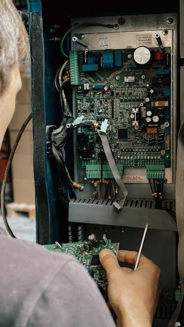
The control module serves as the Aquarite 900’s central hub․ Mount it securely‚ ensuring easy access for operation and monitoring․ Connect the low-voltage cables from the salt cell and any optional accessories․ Power the module using a dedicated circuit‚ adhering to local electrical codes – much like ensuring a secure Facebook login․ Double-check all wiring connections before activation․ Proper grounding is essential for safety‚ mirroring Facebook’s security measures․

Installing the Salt Cell

The salt cell is crucial for chlorine generation․ Install it in the plumbing line after the filter and before any other sanitizing equipment‚ similar to how Facebook connects users․ Ensure proper flow direction as indicated on the cell housing․ Use appropriate plumbing fittings and sealant to prevent leaks․ Tighten connections securely‚ but avoid over-tightening; Like verifying a Facebook account‚ proper installation is vital for optimal performance and longevity․

Understanding the Control Panel Interface

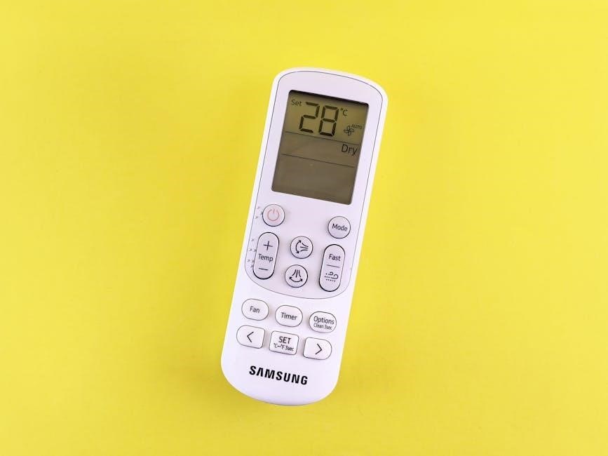
The control panel is your central hub for managing the Aquarite 900․ It displays system status‚ settings‚ and error messages‚ functioning like a Facebook newsfeed․ Familiarize yourself with the buttons for navigation and adjustments․ The interface allows monitoring of salt levels‚ chlorine output‚ and cell performance․ Understanding these features‚ similar to Facebook’s privacy settings‚ ensures efficient operation and troubleshooting․ Regular checks of the display are essential for maintaining optimal water quality․

Display Icons and Their Meanings

The Aquarite 900’s display utilizes icons to communicate system status‚ much like Facebook’s notification symbols․ A solid chlorine icon indicates normal operation‚ while a flashing icon signals low production․ Salt level warnings appear as a salt shaker icon‚ prompting adjustment․ Error codes‚ similar to Facebook’s account block messages‚ require troubleshooting․ A cell cleaning indicator alerts you to maintenance needs․ Understanding these icons is crucial for proactive system management and preventing issues․

Navigating the Menu System

Accessing the Aquarite 900’s menu is similar to finding settings on Facebook – intuitive but requiring exploration․ Use the up/down arrows to scroll through options like ‘Chlorine Level‚’ ‘Salt Reading‚’ and ‘Cell Status․’ The ‘Enter’ button selects‚ while ‘Back’ returns to the previous screen․ Like resetting a Facebook password‚ menu changes require confirmation․ Familiarize yourself with the structure for customized control and efficient troubleshooting‚ ensuring optimal pool sanitation and a user-friendly experience․

Water Chemistry and Balancing

Maintaining proper water chemistry is crucial for Aquarite 900 effectiveness‚ akin to a Facebook profile needing accurate information․ Regularly test pH‚ alkalinity‚ and calcium hardness․ Ideal pH ranges between 7․2-7․8․ Adjust alkalinity before pH․ Salt levels‚ vital for chlorine generation‚ should be within the recommended range (typically 2700-3400 ppm)․ Consistent monitoring‚ like checking Facebook notifications‚ prevents scaling‚ corrosion‚ and ensures optimal sanitation‚ protecting your pool equipment and swimmer comfort․

Salt Level Monitoring and Adjustment

Regularly check salt levels using test strips or a digital meter‚ similar to monitoring Facebook friend requests․ The Aquarite 900 requires a specific salt concentration (2700-3400 ppm) for optimal chlorine production․ Low salt triggers error messages․ Add pool salt gradually‚ following manufacturer instructions‚ and circulate water thoroughly․ High salt levels can cause corrosion․ Adjust slowly‚ retesting after 24 hours․ Consistent monitoring‚ like a Facebook account‚ ensures efficient sanitation and protects the system․

pH Level Management

Maintaining proper pH (7․2-7․8) is crucial for Aquarite 900 effectiveness‚ akin to Facebook’s security measures․ Incorrect pH reduces chlorine’s sanitizing power and causes scaling or corrosion․ Regularly test pH using a reliable kit․ Use pH increaser (soda ash) or pH decreaser (muriatic acid) cautiously‚ following label directions․ Adjust incrementally‚ retesting after several hours․ Balanced pH‚ like a well-maintained Facebook profile‚ ensures water clarity‚ swimmer comfort‚ and extends equipment lifespan․

System Operation Modes

The Aquarite 900 offers distinct modes‚ similar to Facebook’s privacy settings‚ for tailored pool care․ Normal mode provides consistent chlorination based on programmed levels․ Super Chlorination mode‚ activated manually‚ boosts chlorine output for shock treatment after heavy use or algae blooms․ This mode‚ like Facebook’s security features‚ rapidly sanitizes the water․ Automatic mode adjusts output based on demand‚ optimizing efficiency and maintaining ideal water quality․ Understanding these modes ensures optimal performance․

Normal Operation Mode

In Normal Operation‚ the Aquarite 900 functions like a reliable social network connection‚ consistently maintaining chlorine levels․ The system generates chlorine based on the user-defined production percentage and programmed run times․ This mode prioritizes consistent sanitation‚ mirroring Facebook’s continuous updates․ It’s ideal for routine pool maintenance‚ ensuring water clarity and safety․ Regular monitoring of salt levels and water balance is crucial for optimal performance within this standard operating procedure․

Super Chlorination Mode

Super Chlorination Mode‚ akin to a Facebook “block” for contaminants‚ temporarily boosts chlorine production․ This is activated to quickly address issues like algae blooms or after heavy pool usage‚ similar to resetting a password․ The Aquarite 900 operates at 100% output for a defined duration‚ typically 24-72 hours․ Following this‚ it reverts to Normal Operation․ Regularly test water chemistry during and after Super Chlorination to ensure safe and balanced levels‚ preventing account blockage!

Troubleshooting Common Issues

Like encountering login problems on Facebook‚ the Aquarite 900 can present challenges․ Common issues include low salt readings (verify salt levels and cell connections) and cell cleaning indicators (prompting manual cleaning)․ Error messages require careful attention; consult the display icon guide․ If the system appears “blocked‚” check power supply and connections․ Persistent problems may necessitate contacting customer support‚ similar to seeking help with a compromised account․

Low Salt Reading Errors

A “low salt” error‚ akin to Facebook account access issues‚ indicates insufficient salt for chlorine generation․ First‚ verify the salt level using a reliable test kit; maintain recommended levels․ Inspect the salt cell for scaling‚ hindering performance․ Ensure proper salt distribution‚ avoiding clumping․ Check the salt reservoir for adequate supply․ If issues persist‚ examine wiring connections and the control module’s sensor functionality‚ mirroring troubleshooting a blocked Facebook account․

Cell Cleaning Indicators

The Aquarite 900 displays indicators signaling the need for cell cleaning‚ similar to Facebook’s notification system․ A flashing light or specific error code alerts you to scale buildup‚ reducing chlorine production efficiency․ Regular inspection is crucial․ Ignoring these signals‚ like unaccepted Facebook friend requests‚ diminishes performance․ Prompt cleaning restores optimal operation‚ ensuring sanitized pool water․ Monitor the control panel frequently for these vital maintenance reminders‚ preventing system inefficiencies․

Cell Cleaning and Maintenance

Maintaining a clean salt cell is vital for optimal Aquarite 900 performance‚ much like keeping a Facebook profile updated․ Regular inspection and cleaning prevent scale buildup‚ ensuring efficient chlorine generation․ Use a diluted muriatic acid solution‚ following safety guidelines․ Like addressing blocked Facebook accounts‚ prompt action resolves issues․ Thorough rinsing is essential post-cleaning․ Consistent maintenance extends the cell’s lifespan and guarantees consistently sanitized‚ sparkling pool water‚ mirroring a well-maintained online presence․

Manual Cell Cleaning Procedure

To manually clean your Aquarite 900 cell‚ begin by isolating the power․ Carefully remove the cell and visually inspect for scale buildup – similar to checking Facebook privacy settings․ Mix a solution of one part muriatic acid to four parts water‚ ensuring proper ventilation․ Submerge the cell‚ allowing it to soak for 15-20 minutes․ Rinse thoroughly with clean water‚ re-install‚ and restore power․ This process‚ like resolving Facebook login issues‚ requires patience and precision․

Frequency of Cell Cleaning

The frequency of Aquarite 900 cell cleaning depends on water hardness and usage‚ much like Facebook’s algorithm changes․ Generally‚ inspect the cell monthly and clean when the unit indicates a “CLEAN” message or chlorine production drops․ In areas with hard water‚ cleaning may be needed every 3-6 months․ Regular monitoring‚ similar to checking Facebook notifications‚ prevents scale buildup and maintains optimal performance․ Consistent cleaning ensures efficient sanitization and extends the cell’s lifespan․

Winterizing the Aquarite 900 System

Proper winterization‚ much like securing a Facebook account‚ protects your Aquarite 900 from freeze damage․ First‚ drain the system completely‚ including the pump‚ filter‚ and salt cell․ Remove the cell and thoroughly rinse it․ Next‚ blow out the plumbing lines with compressed air․ Store the cell indoors in a dry location․ Disconnect the control module and protect it from moisture․ This prevents costly repairs and ensures a smooth startup next season․

Draining the System

Similar to deleting a Facebook account‚ completely draining your Aquarite 900 system is crucial for winter protection․ Begin by turning off the pump and power to the unit․ Open all drain plugs on the filter‚ pump‚ and heater․ Allow sufficient time for complete drainage․ For the salt cell‚ disconnect it and drain any remaining water․ This prevents freezing and potential cracking of components‚ safeguarding your investment against costly repairs during colder months․

Protecting the Salt Cell from Freezing

Like finding someone on Facebook‚ protecting your Aquarite 900’s salt cell requires focused effort․ After draining‚ thoroughly rinse the cell with fresh water to remove residual salt․ Store the cell indoors‚ in a dry location‚ away from direct sunlight․ If indoor storage isn’t possible‚ heavily insulate the cell․ Freezing can severely damage the cell’s plates‚ rendering it ineffective and requiring replacement – a costly outcome to avoid․

Safety Precautions and Warnings

Similar to Facebook’s account security measures‚ prioritizing safety with the Aquarite 900 is crucial․ Always disconnect power before servicing․ Never attempt to repair the control module yourself; contact qualified technicians․ Handle chemicals cautiously‚ wearing appropriate protective gear․ Ensure proper grounding to prevent electrical shock․ Keep the control module dry and protected from the elements․ Follow all local electrical codes and regulations during installation and operation․

Electrical Safety Guidelines

Like Facebook’s security protocols protecting user data‚ electrical safety is paramount․ Always disconnect power before inspecting or servicing the Aquarite 900․ Ensure proper grounding to prevent shocks․ Use only approved wiring and connectors․ Never operate with damaged cords or plugs․ Avoid exposure to moisture․ Installation must comply with local electrical codes․ If unsure‚ consult a qualified electrician․ Regularly inspect wiring for damage‚ mirroring Facebook’s constant security checks․

Chemical Handling Precautions

Similar to Facebook’s community standards‚ responsible chemical handling is crucial․ Always wear protective gear – gloves and eye protection – when handling pool chemicals․ Never mix different chemicals together․ Add chemicals to water‚ not water to chemicals․ Store chemicals in a cool‚ dry‚ well-ventilated area‚ away from children and pets․ Follow label instructions carefully․ Spills require immediate cleanup․ Proper ventilation is key‚ like Facebook’s open communication policy․

Warranty Information and Support

Like Facebook’s user support resources‚ the Aquarite 900 comes with a limited warranty․ This covers defects in materials and workmanship for a specified period․ The warranty doesn’t cover damage from misuse or improper installation․ Retain your proof of purchase for warranty claims․ For support‚ consult the troubleshooting section or contact customer service․ Details are available online or in the included documentation‚ ensuring a connected experience․

Aquarite 900 Warranty Details

Similar to Facebook’s account protection measures‚ the Aquarite 900 warranty safeguards against manufacturing flaws․ The standard warranty period is typically one to two years from the date of purchase․ It covers the control module and salt cell‚ excluding wear items․ Damage due to incorrect water chemistry‚ freezing‚ or unauthorized repairs voids the warranty․ Proof of purchase is essential for any claim submission‚ mirroring Facebook’s verification processes․

Contacting Customer Support

Like seeking help on Facebook when encountering account issues‚ Aquarite 900 support is readily available․ You can reach them via phone during business hours‚ or through their website’s online support portal․ Detailed FAQs and troubleshooting guides are also accessible online‚ similar to Facebook’s help center․ Expect prompt assistance with technical questions‚ warranty claims‚ or operational guidance․ Documenting your system’s model and serial number will expedite the support process․

Advanced Settings and Customization

Similar to customizing your Facebook profile‚ the Aquarite 900 offers advanced settings for tailored pool care․ Adjust chlorine production levels based on sunlight exposure and bather load․ Program custom schedules to optimize sanitation during peak usage times․ Fine-tune settings to match your specific pool volume and water chemistry․ Explore boost modes for rapid chlorine generation after heavy use‚ ensuring consistently clean and safe swimming conditions․

Adjusting Chlorine Production Levels

Like managing Facebook privacy settings‚ controlling chlorine output is crucial․ The Aquarite 900 allows precise adjustment of chlorine production‚ typically expressed as a percentage․ Increase levels during hot weather or periods of high bather load‚ mirroring increased social activity․ Conversely‚ reduce output during cooler months or when the pool is less used․ Regularly test water chemistry to ensure optimal sanitation and prevent imbalances‚ similar to monitoring your online presence․

Programming Schedules

Similar to scheduling Facebook posts‚ the Aquarite 900 enables customized chlorination schedules․ Program different production levels for various times of the day or week‚ optimizing efficiency and sanitation․ Consider peak usage times and sunlight exposure when creating your schedule․ This feature minimizes chemical usage while maintaining consistent water quality‚ much like targeted social media campaigns․ Review and adjust schedules seasonally to adapt to changing conditions and bather loads․

Frequently Asked Questions (FAQ)

Like troubleshooting Facebook login issues‚ common Aquarite 900 questions involve low salt readings or cell cleaning prompts․ Is the unit displaying an error code? Ensure adequate salt levels and a properly functioning salt cell․ Why isn’t chlorine being produced? Check power supply and cell connections․ Can I adjust the super chlorination duration? Yes‚ via the control panel․ Regular maintenance‚ similar to updating your Facebook profile‚ ensures optimal performance․

aprilaire thermostat install manual

Aprilaire Thermostat Installation Manual: A Comprehensive Plan

Welcome! This manual details the installation, configuration, and maintenance of your Aprilaire thermostat, offering a step-by-step guide for optimal performance and indoor air quality.

Explore detailed instructions, troubleshooting tips, and access to downloadable manuals for both current and discontinued Aprilaire products.

Aprilaire thermostats represent a commitment to superior indoor air quality and home comfort. For decades, Aprilaire has been a leader in whole-house air solutions, extending that expertise into innovative thermostat technology. These thermostats aren’t simply temperature controllers; they are integrated systems designed to manage humidity, ventilation, and air purification alongside heating and cooling.

The 8920W series, a prominent example, showcases a touch screen interface with integrated indoor air quality solutions. Aprilaire thermostats cater to diverse needs, offering models powered by AC, batteries, or a combination of both, ensuring continuous operation even during power outages thanks to memory backup functionality.

This installation manual provides comprehensive guidance, from initial setup and wiring to advanced configuration of system settings. Understanding your thermostat’s capabilities and following these instructions will unlock its full potential, creating a healthier and more comfortable living environment. Proper installation is crucial for optimal performance and longevity.

Understanding the 8920W Series

The Aprilaire 8920W is a touch screen, Wi-Fi enabled thermostat distinguished by its integrated indoor air quality (IAQ) solutions. This series goes beyond basic temperature control, actively monitoring and managing crucial IAQ parameters for a healthier home environment. It offers advanced features like humidity control, ventilation management, and compatibility with Aprilaire air purification systems.

Key features include a user-friendly interface, remote access via Wi-Fi, and customizable scheduling. The 8920W can operate on AC power with optional battery backup, or solely on batteries, providing flexibility during installation. Its memory backup ensures settings are retained even during power interruptions.

This thermostat allows for manual activation of system outputs for testing purposes, ensuring proper functionality. Accessing existing thermostat settings is straightforward, enabling seamless integration with existing HVAC systems. Understanding these features is vital for maximizing the benefits of the 8920W series.

Safety Precautions Before Installation

Prior to commencing any installation work, disconnect power to your HVAC system at the breaker panel to prevent electrical shock. Verify the power is off using a non-contact voltage tester. Always adhere to local electrical codes and regulations throughout the installation process.

Exercise caution when working with wiring; incorrect connections can damage the thermostat or HVAC equipment. If you are uncomfortable working with electrical wiring, consult a qualified HVAC technician. Wear appropriate safety glasses to protect your eyes from debris.

Be mindful of potential hazards when mounting the thermostat, ensuring a secure attachment to the wall or junction box. Avoid installing the thermostat in areas exposed to direct sunlight, drafts, or extreme temperatures. Read all instructions carefully before beginning, and retain this manual for future reference.

Tools and Materials Required

For a successful Aprilaire thermostat installation, gather these essential tools: a Phillips head screwdriver, a flathead screwdriver, wire strippers, a wire connector, a level, a drill with appropriate drill bits, and a non-contact voltage tester; A pencil is useful for marking mounting locations.

Necessary materials include the Aprilaire thermostat itself, mounting screws (typically provided with the thermostat), wire labels for identification, and potentially a new thermostat wire if the existing wiring is insufficient or damaged. Depending on the power source, you may need batteries or access to AC power wiring.

Consider having a digital multimeter available for testing voltage and continuity. A small ladder or step stool may be needed to reach the installation location. Ensure all materials are readily accessible before starting the installation process to streamline the workflow.

Identifying Thermostat Components

The Aprilaire thermostat features a touchscreen display for intuitive control and monitoring of your home’s climate. Locate the battery compartment, typically on the back or side, housing the battery backup for clock retention during power outages. A reset button, often found under the battery cover, restores factory defaults.

Key components include the terminal block for wiring connections, clearly labeled for various system functions (R, C, W, Y, G, etc.). Identify the internal sensors responsible for temperature and humidity readings. The housing provides protection for the internal electronics.

Familiarize yourself with the Wi-Fi connectivity indicator, signaling a successful network connection. Understand the function of any integrated indoor air quality sensors, if applicable to your model (like the 8920W series). Refer to the specific model’s diagram in the manual for precise component locations.

Installation Location Recommendations

Optimal thermostat placement is crucial for accurate temperature readings and efficient system operation. Mount the thermostat on an interior wall, avoiding direct sunlight, drafts, and proximity to heat sources like lamps or appliances. Choose a frequently occupied space to ensure representative temperature sensing.

Recommended height is approximately 5 feet above the floor. Maintain a minimum distance of 18 inches from exterior walls to minimize the influence of outside temperatures. The thermostat can be conveniently mounted to a vertical junction box, simplifying installation.

Avoid locations near doorways, windows, or areas with poor air circulation. Do not install in areas prone to excessive moisture or dust. Proper placement ensures reliable performance and accurate control of your home’s heating and cooling system.

Mounting the Thermostat – Interior Wall Guidelines

Prior to mounting, ensure the chosen interior wall meets the location recommendations – away from drafts, sunlight, and heat sources. Use the provided mounting template to mark the screw holes accurately. Carefully drill pilot holes to prevent wall damage, using appropriate drill bits for your wall type.

Secure the mounting plate to the wall using the screws included in the package. Ensure the plate is level for a professional appearance and accurate thermostat operation. Gently snap the thermostat onto the mounted plate, verifying a secure connection.

Double-check the thermostat’s stability and alignment. A firmly mounted thermostat is essential for reliable performance. Avoid over-tightening screws, which could damage the wall or the thermostat housing.

Mounting to a Junction Box

For installations utilizing a vertical junction box, ensure the box is securely mounted to the wall and properly rated for the thermostat’s weight. Remove the junction box cover plate carefully, exposing the wiring connections. Align the thermostat’s mounting plate with the screw holes on the junction box.

Secure the mounting plate to the junction box using the screws provided. Ensure a snug fit, but avoid over-tightening, which could damage the box or the thermostat. Verify the plate is level before proceeding. Gently snap the thermostat onto the mounted plate, confirming a secure connection.

Double-check the stability of the thermostat and the integrity of the wiring connections. A secure mounting to the junction box provides a stable and safe installation.

Avoiding Incorrect Mounting Locations

To ensure accurate temperature readings and optimal performance, avoid mounting the thermostat in locations prone to drafts, direct sunlight, or near heat-generating appliances; Do not install the thermostat on exterior walls without adequate insulation, as this can lead to inaccurate readings.

Avoid areas near windows, doors, fireplaces, or kitchen appliances. These locations experience fluctuating temperatures that will compromise the thermostat’s ability to maintain a consistent indoor climate. Also, refrain from mounting the thermostat in areas with poor air circulation or where it may be obstructed by furniture or curtains.

Incorrect placement can result in inefficient heating and cooling, increased energy consumption, and inaccurate temperature control. Prioritize a stable, centrally located interior wall for best results.

Wiring the Thermostat – AC Power

When connecting to AC power, always disconnect power at the breaker before beginning any wiring. Identify the appropriate terminals for your system – typically labeled R, C, W, Y, and G. The ‘R’ terminal is for 24VAC power, ‘C’ is the common wire, ‘W’ activates heating, ‘Y’ activates cooling, and ‘G’ controls the fan.

Carefully connect each wire to the corresponding terminal, ensuring a secure connection. If a ‘C’ wire is not present, a common wire adapter may be required. Batteries are optional when using AC power, serving solely as a backup for the clock during power outages.

Double-check all connections before restoring power at the breaker. Incorrect wiring can damage the thermostat or your HVAC system. If unsure, consult a qualified HVAC technician.

Wiring the Thermostat – Battery Power

For battery-powered operation, install the required batteries (typically AA) into the battery compartment located under the thermostat’s cover. Ensure correct polarity as indicated inside the compartment. The thermostat will power on automatically once batteries are installed, displaying the initial setup screen.

While batteries can power the thermostat completely, connecting to AC power provides a more reliable and consistent power source. When AC power is present, batteries act as a backup, maintaining the clock and settings during brief power interruptions.

Regularly check the battery level indicator on the thermostat display. Replace batteries when the low battery icon appears to prevent loss of settings or functionality. Proper battery installation ensures accurate timekeeping and consistent operation.

Battery Backup Functionality

The Aprilaire thermostat features a robust memory backup system, safeguarding your personalized settings even during power outages. When AC power is interrupted, the thermostat seamlessly switches to battery power, preserving your programmed schedule, temperature preferences, and system configurations.

This functionality ensures minimal disruption to your comfort and energy savings. The clock continues to run accurately, and the thermostat maintains its operational state, preventing the need for reprogramming upon power restoration.

Batteries serve as a crucial safeguard, particularly for systems reliant on precise timing or complex scheduling. Regularly check battery levels to guarantee uninterrupted backup power. The thermostat’s memory retains settings even with prolonged outages, offering peace of mind and consistent performance.

Initial Thermostat Setup

Upon powering on your Aprilaire thermostat, the initial setup process will guide you through essential configurations. This includes selecting your preferred language, date, and time settings. The thermostat will then prompt you to identify your heating and cooling system type – crucial for optimal operation.

Carefully follow the on-screen instructions to accurately define your system. Incorrect settings can lead to inefficient performance or system malfunctions. You’ll also be asked to configure basic preferences, such as temperature display format (Fahrenheit or Celsius).

Take your time during this phase to ensure accurate input. Proper initial setup lays the foundation for a comfortable and energy-efficient home environment. Refer to the installation instructions for specific guidance related to your system type and thermostat model.

Entering Test Mode & Output Activation

To verify proper wiring and functionality, your Aprilaire thermostat features a dedicated test mode. Accessing this mode allows you to manually activate each system output – heating, cooling, fan, and auxiliary heat – individually. This confirms that each component is correctly connected and responding to the thermostat’s signals.

The procedure for entering test mode typically involves a specific sequence of button presses, detailed in your model’s installation instructions. Once in test mode, you can cycle through each output, observing its operation. Carefully monitor each stage to ensure it activates as expected.

This step is crucial for troubleshooting installation issues. If an output fails to activate, re-examine the wiring connections and consult the troubleshooting section of this manual. Remember to exit test mode once all outputs have been verified.

Resetting to Factory Defaults

Occasionally, you may need to restore your Aprilaire thermostat to its original factory settings. This is useful when troubleshooting complex issues, preparing the thermostat for a new system, or simply clearing personalized configurations. The reset process erases all custom settings, returning the thermostat to its out-of-the-box state.

To initiate a factory reset, locate the reset button. It’s typically found under the battery cover, often requiring a small tool like a paperclip to access. Press and hold the reset button for a specified duration – usually several seconds – until the thermostat restarts.

Be aware that resetting to factory defaults will require you to re-enter all your preferred settings, including date, time, and system configurations. Consult your installation manual for the precise reset procedure for your specific Aprilaire model.

Configuring System Settings

After initial setup, configuring your Aprilaire thermostat’s system settings is crucial for optimal performance and personalized comfort. These settings dictate how the thermostat interacts with your heating and cooling systems, ensuring efficient operation. Accessing these settings typically involves navigating through the thermostat’s touchscreen interface or utilizing the accompanying mobile app.

Key settings include defining your heating and cooling system types (e.g., furnace, heat pump, air conditioner), setting temperature preferences, and establishing scheduling parameters. You can customize temperature hold durations, create daily or weekly schedules, and configure fan operation modes.

For detailed guidance, refer to your specific model’s manual. Understanding your existing thermostat’s settings before installation can streamline the configuration process; Proper configuration maximizes energy savings and ensures consistent comfort throughout your home.

Accessing Existing Thermostat Settings

Before removing your old thermostat, documenting its current settings is highly recommended. This information will be invaluable when configuring your new Aprilaire thermostat, ensuring a smooth transition and minimizing disruption to your comfort. The method for accessing these settings varies significantly depending on the make and model of your existing thermostat.

Many older thermostats require removing the cover to reveal physical dials or switches representing temperature settings, fan modes, and scheduling options. Digital thermostats typically feature menu-driven interfaces accessible via buttons or a touchscreen. Carefully note each setting, including temperature setpoints, schedule times, and any customized preferences.

Refer to the installation instructions for your existing thermostat for specific guidance on accessing its settings. Photographing the display or creating a written record is a helpful practice. This proactive step will simplify the installation process and ensure your new Aprilaire thermostat is configured to your exact needs.

Understanding System Outputs

Aprilaire thermostats control various system outputs to manage your home’s heating, cooling, and ventilation. These outputs are essentially signals sent to your HVAC equipment, instructing it to turn on or off specific components. Common outputs include signals for the furnace, air conditioner, fan, and humidifier.

Understanding these outputs is crucial for proper wiring and troubleshooting. The thermostat’s wiring terminals correspond to specific outputs, and incorrect connections can lead to system malfunctions. For example, the ‘R’ terminal typically provides power, while ‘W’ activates the heating system.

The 8920W series allows for manual activation of each output individually during testing. This feature helps verify correct wiring and ensures each component is functioning as expected. Refer to the wiring diagram in your installation manual to identify each output and its corresponding terminal. Properly identifying and connecting these outputs is essential for a fully functional system.

Troubleshooting Common Issues

Encountering problems with your new Aprilaire thermostat? Several common issues can arise during or after installation. A frequent concern is the thermostat not powering on; check the AC power connection or battery levels first. If the display is blank, attempt a reset using the button under the battery cover.

Incorrect temperature readings can often be resolved by verifying the thermostat’s location isn’t near heat sources or drafts. Communication failures with the HVAC system usually indicate wiring errors – double-check all connections against the wiring diagram. For Wi-Fi connectivity issues, ensure your network is stable and the password is correct.

Remember the memory backup saves settings during power outages, but a full reset to factory defaults might be needed for complex problems. Consult the full installation manual or Aprilaire’s support resources for detailed troubleshooting steps and diagrams. Don’t hesitate to seek professional assistance if issues persist.

Memory Backup Functionality Explained

Aprilaire thermostats are equipped with a valuable memory backup feature, designed to protect your personalized settings during unexpected power interruptions. This functionality ensures that your programmed schedules, temperature preferences, and system configurations are retained even if the AC power is lost.

The memory is sustained by the batteries installed in the thermostat, even when the unit is primarily powered by AC electricity. These batteries act as a reliable backup, preserving your settings for an extended period. However, it’s important to note that batteries have a limited lifespan and should be replaced periodically to maintain this functionality.

Without this backup, a power outage would necessitate a complete re-configuration of your thermostat. The memory backup provides peace of mind, ensuring a seamless return to your desired settings once power is restored. Regular battery checks are recommended for optimal performance.

Downloading Aprilaire Owners Manuals (PDFs)

Aprilaire provides convenient access to a comprehensive library of owner’s manuals in PDF format, readily available for download directly from their website. This resource encompasses both current models and discontinued products, ensuring support for a wide range of Aprilaire systems.

The manuals are meticulously organized by product type, simplifying the search process and allowing users to quickly locate the documentation specific to their thermostat. A direct link to a compatible PDF reader is often provided, facilitating immediate access to the manuals without requiring additional software installation.

Downloading the PDF allows for offline viewing and printing, offering flexibility and convenience. These manuals contain detailed installation instructions, operating guidelines, troubleshooting tips, and warranty information. Accessing these resources empowers users to effectively manage and maintain their Aprilaire thermostat, maximizing its performance and longevity.

Maintaining Your Aprilaire Thermostat

Regular maintenance ensures the continued optimal performance and longevity of your Aprilaire thermostat. Periodically, gently clean the thermostat’s exterior with a soft, dry cloth to remove dust and debris, avoiding abrasive cleaners or liquids. Inspect the battery compartment (if applicable) and replace batteries as needed, even if the thermostat is AC-powered, as they provide backup during power outages.

Ensure the thermostat is free from obstructions that could interfere with accurate temperature readings. Avoid exposing the thermostat to extreme temperatures or humidity. Familiarize yourself with the reset button, located under the battery cover, for restoring factory defaults if necessary.

Proactive maintenance, combined with referencing the owner’s manual for specific model instructions, will help you troubleshoot minor issues and prevent potential problems, maximizing your investment in an Aprilaire thermostat.

Indoor Air Quality Solutions Integration (8920W)

The Aprilaire 8920W series uniquely integrates with Aprilaire’s comprehensive indoor air quality (IAQ) solutions. This thermostat isn’t just for temperature control; it’s a central hub for managing humidity, ventilation, and air purification systems. Seamlessly connect to compatible Aprilaire Healthy Air Systems, including whole-house humidifiers, dehumidifiers, and air purifiers.

Monitor and control IAQ parameters directly from the thermostat’s touchscreen interface or remotely via the mobile app. Customize settings to optimize indoor air quality based on your preferences and needs. Benefit from features like humidity control, fresh air intake management, and air purification monitoring.

Leverage the 8920W’s capabilities to create a healthier and more comfortable home environment, proactively addressing potential IAQ issues and enhancing overall well-being.

Aprilaire 8400 Series Installation Overview

The Aprilaire 8400 Series thermostats offer reliable and straightforward installation, designed for compatibility with a wide range of HVAC systems. Installation typically involves mounting the thermostat to a wall or existing junction box, followed by careful wiring connections. Ensure power is off before commencing any electrical work.

Refer to the dedicated 8400 Series installation instructions manual (available for download as a PDF) for detailed wiring diagrams specific to your system configuration. Pay close attention to identifying the correct terminals for heating, cooling, and common wires. Proper wiring is crucial for optimal performance and preventing system malfunctions.

Once wired, the thermostat can be powered on and configured with your desired settings. The manual provides guidance on setting the date, time, and system preferences. Models like 8463, 8465, 8466, 8444, 8446, and 8448 share similar installation principles.

Discontinued Product Manuals Access

Aprilaire understands the need for support even after products are discontinued. Accessing manuals for older Aprilaire thermostats is readily available through their official website. A comprehensive archive of PDF owner’s manuals is organized by product type, simplifying the search process.

Whether you own a legacy model or require documentation for troubleshooting, these resources provide valuable information. The online library includes manuals for thermostats no longer in production, ensuring continued usability and repair capabilities. A direct link to a PDF reader is often provided for convenient access.

Locate your specific model number to quickly find the corresponding manual. These archived documents contain essential details regarding installation, operation, and maintenance procedures. Don’t hesitate to utilize this resource for any questions or concerns regarding your discontinued Aprilaire thermostat.

Resources for Further Assistance

Beyond this manual, Aprilaire offers a wealth of support options for your thermostat needs. Their official website serves as a central hub for FAQs, troubleshooting guides, and contact information. For direct assistance, a dedicated customer support team is available via phone or email, ready to address your specific concerns.

Explore the Aprilaire online community forums, where users share experiences, solutions, and helpful tips. These forums provide a collaborative environment for resolving common issues and learning best practices. Additionally, authorized Aprilaire dealers and installers can offer professional guidance and installation services.

Don’t hesitate to leverage these resources to ensure a seamless experience with your Aprilaire thermostat. From detailed documentation to expert support, Aprilaire is committed to providing comprehensive assistance throughout the product lifecycle.

ge steam washer dryer combo manual

GE Steam Washer Dryer Combo Manual: A Comprehensive Guide

Welcome! This detailed manual provides essential guidance for your GE Profile Washer Dryer Combo, offering insights into operation and maximizing its innovative features․

This resource, compiled by Andrea Barnes and Liam, will help you navigate the latest advancements in all-in-one laundry solutions, including heat pump technology․

GE washer dryer combos represent a significant evolution in laundry appliances, particularly gaining traction in North America after decades of popularity in Europe and Asia․ These all-in-one units offer a compelling solution for individuals facing space constraints, eliminating the need for separate washing and drying machines․

Unlike traditional setups, GE combos seamlessly integrate both functions into a single appliance, streamlining the laundry process․ The emergence of new, larger combo units, incorporating advanced heat pump technology, provides efficient and effective cleaning and drying capabilities․

This manual focuses on GE steam washer dryer combos, highlighting their unique features and benefits․ These appliances are designed for convenience, offering a complete laundry solution in a single footprint․ Understanding the capabilities of your GE combo will ensure optimal performance and longevity, as detailed by experts like Andrea Barnes․

Understanding Combo Unit Benefits

Space Optimization: The primary advantage of a GE washer dryer combo is its compact design, ideal for apartments, condos, or homes with limited laundry room space․ Eliminating the need for two separate appliances frees up valuable floor space․

Convenience: Combo units streamline the laundry process․ Clothes can transition directly from the wash cycle to the dry cycle without manual transfer, saving time and effort․ This is particularly beneficial for busy lifestyles․

Cost Savings: While the initial investment might be higher, combos can potentially reduce costs associated with purchasing and maintaining two separate machines․ Furthermore, advanced heat pump technology, as found in newer models, enhances energy efficiency․

Simplified Laundry Routine: A single appliance simplifies laundry management, reducing the number of tasks and steps involved․ As noted by reviewers, this all-in-one solution is a “dream” for those seeking a hassle-free laundry experience․

Key Features of GE Steam Washer Dryer Combos

Steam Technology: GE Steam Washer Dryer Combos utilize steam to sanitize clothes, reduce wrinkles, and refresh fabrics․ Steam cycles penetrate deeply, offering a more thorough clean and minimizing the need for ironing․

Smart Connectivity: Many models boast Wi-Fi connectivity, enabling remote control and monitoring via smartphone apps․ This allows users to start or pause cycles, receive notifications, and access smart features from anywhere․

Advanced Wash Cycles: These combos offer a variety of specialized wash cycles tailored to different fabric types and soil levels, including delicate, heavy-duty, and quick wash options․

Heat Pump Drying: Newer GE combos incorporate heat pump technology, known for its energy efficiency and gentle drying capabilities․ This technology recycles heat, reducing energy consumption and protecting clothes from excessive heat damage․

Getting Started: Installation & Setup

Preparation is key! Carefully unpack your GE combo, inspect for damage, and ensure proper water supply, electrical connections, and leveling for optimal performance․

Unboxing and Initial Inspection

Carefully unpack your new GE Steam Washer Dryer Combo, taking inventory of all included components․ Begin by removing the outer packaging, then gently lift away the protective materials inside the drum․ Inspect the unit thoroughly for any signs of shipping damage – dents, scratches, or broken parts․

Compare the contents against the included parts list to ensure everything is present․ This typically includes the combo unit itself, a water inlet hose, a drain hose, an owner’s manual, and potentially leveling feet or accessories․ Document any damage immediately with photographs and contact the retailer or GE customer support․

Retain all packaging materials until you are completely satisfied with the condition of the appliance․ Do not discard the shipping bolts until the unit is properly leveled and secured, as these were used to stabilize the drum during transport․ Proper initial inspection prevents future issues!

Water Supply Connection

Connect the water inlet hose to a cold water supply with adequate pressure – typically between 20 and 120 psi․ Ensure the connection is secure to prevent leaks, using Teflon tape on the threads if necessary․ Do not use hot water, as this unit is designed for cold water intake only․

Attach the other end of the hose to the designated inlet valve on the back of the combo unit, again ensuring a tight connection․ Check for kinks or bends in the hose that could restrict water flow․ Consider using a new hose to avoid potential issues with older, worn-out connections;

Slowly turn on the water supply and inspect the connections for any leaks․ Tighten connections further if needed․ Proper water connection is crucial for optimal washing performance and preventing water damage․

Electrical Requirements and Grounding

This GE combo unit requires a dedicated 120V, 60Hz electrical circuit with a 15-amp breaker․ Do not use extension cords or adapters; plug directly into a grounded outlet․ Improper electrical connection can pose a safety hazard and void the warranty․

Grounding is essential for safety․ The unit must be properly grounded to prevent electric shock․ The power cord includes a grounding wire – do not remove or alter it․ If the outlet is not grounded, consult a qualified electrician to install a grounded outlet․

Verify the voltage matches the unit’s specifications․ Never attempt to modify the plug to fit a different outlet․ Regularly inspect the power cord for damage and replace it if necessary․ A safe electrical setup is paramount for reliable operation;

Leveling the Unit

Proper leveling is crucial for optimal performance and to minimize vibration and noise during operation․ Use a bubble level to check the unit’s stability on the floor․ Adjustable feet are located at each corner of the appliance; rotate them clockwise to raise the unit and counterclockwise to lower it․

Ensure all four feet are firmly in contact with the floor․ If the floor is uneven, use shims under the feet to achieve a level position․ Continuously check with the bubble level as you adjust each foot․ A properly leveled unit will prevent excessive movement during the wash and dry cycles․

Tighten the lock nuts on the adjustable feet after leveling to prevent accidental movement․ Re-check the leveling periodically, especially after moving the unit․ A stable base contributes to the longevity and efficiency of your GE combo․

Operating Your GE Combo: Wash Cycles

Explore diverse wash cycles – Normal, Delicates, Heavy Duty, and Quick Wash – alongside innovative Steam Wash options, designed for optimal cleaning and fabric care․

Normal/Regular Wash Cycle

The Normal/Regular Wash Cycle is your go-to setting for everyday laundry loads․ This cycle is expertly calibrated to effectively clean moderately soiled items, including clothing, towels, and linens․ It utilizes a balanced combination of wash actions and water temperatures to deliver consistently fresh results․

Load Capacity: This cycle performs optimally with medium-sized loads․ Avoid overloading the drum to ensure thorough cleaning and prevent damage to your garments․ Refer to the capacity guidelines in the full manual for specific weight recommendations․

Water Temperature: The default water temperature for the Normal cycle is typically warm, but you can customize this setting based on your fabric care needs․ Colder water is gentler on colors and helps conserve energy, while warmer water is more effective at removing stubborn stains․

Soil Level: Adjust the soil level setting to match the level of dirt and grime in your laundry․ For lightly soiled items, select a lower soil level to conserve water and energy․ For heavily soiled items, choose a higher soil level for a more intensive cleaning action․

Delicates/Hand Wash Cycle

The Delicates/Hand Wash Cycle is specifically designed for your most fragile garments, offering a gentle cleaning experience․ This cycle utilizes a slow wash action and cool water temperatures to protect delicate fabrics like lingerie, silk, lace, and hand-washables․

Gentle Action: The cycle’s tumbling action is significantly reduced compared to the Normal cycle, minimizing friction and preventing stretching or damage to delicate fibers․ This ensures your treasured items remain in pristine condition․

Water Temperature: Cool water is automatically selected for this cycle, as warm or hot water can cause shrinkage or color fading in delicate fabrics․ This preserves the vibrancy and integrity of your clothes․

Load Size: It’s crucial to wash small loads on the Delicates cycle to allow garments ample space to move freely and receive thorough cleaning․ Overloading can compromise the gentle wash action and potentially damage items․

Heavy Duty/Bulky Items Cycle

The Heavy Duty/Bulky Items Cycle is engineered to tackle your toughest laundry challenges – think bedding, towels, jeans, and work clothes․ This cycle employs a powerful wash action and extended wash times to effectively remove deep-seated dirt and grime․

Robust Cleaning: Expect vigorous tumbling and a higher spin speed to extract more water, ensuring thorough cleaning and efficient drying․ This cycle is ideal for items that require a more intense cleaning process․

Water Levels & Temperature: The washer automatically adjusts water levels to accommodate bulky loads, while maintaining optimal water temperatures for effective stain removal․ Hot water is typically used, but adjustments may be possible․

Load Considerations: While designed for large items, avoid overloading the machine․ Ensure items have enough room to move freely for optimal cleaning․ Distribute the load evenly around the drum to maintain balance during the cycle․

Quick Wash Cycle

The Quick Wash Cycle is your go-to solution for lightly soiled items that need a refresh․ Designed for convenience, this cycle delivers a satisfactory clean in a significantly reduced timeframe – typically under 30 minutes․ It’s perfect for everyday clothes, gym wear, or items you need in a hurry․

Speed & Efficiency: This cycle utilizes a faster wash and spin speed, minimizing water usage and cycle duration․ While prioritizing speed, it still maintains effective cleaning performance for lightly soiled loads․

Load Size: The Quick Wash cycle is best suited for smaller loads․ Overloading can compromise cleaning effectiveness․ For larger or heavily soiled items, opt for a more comprehensive wash cycle․

Temperature Settings: Typically, the Quick Wash cycle uses cold water to conserve energy and protect delicate fabrics; However, some models may offer temperature adjustments․

Steam Wash Options & Benefits

Harnessing the Power of Steam: GE Steam Washer Dryer Combos offer innovative steam wash options designed to elevate your laundry experience․ Steam penetrates fabrics more effectively than water alone, resulting in superior cleaning and sanitization․

Sanitize Cycle: Utilizing high-temperature steam, the sanitize cycle eliminates 99․9% of common household bacteria, providing peace of mind for items like bedding, baby clothes, and towels․ This is especially beneficial for allergy sufferers․

Allergen Cycle: Specifically engineered to remove allergens like dust mites and pet dander, the allergen cycle is ideal for sensitive skin and those prone to allergies․

Wrinkle Care: Steam helps relax fibers, reducing wrinkles and minimizing the need for ironing․ This feature is particularly useful for delicate garments and dress shirts․

Operating Your GE Combo: Dryer Cycles

Explore Drying Options: Your GE combo offers diverse dryer cycles – Normal, Delicates, Heavy Duty, and Air Fluff – alongside beneficial Steam Dry features for optimal results․

Normal/Medium Heat Drying

Utilizing the Normal/Medium Heat Drying cycle is ideal for everyday laundry loads, encompassing items like cottons, linens, and durable synthetics․ This setting provides a balanced approach to drying, effectively removing moisture without subjecting fabrics to excessive heat that could cause shrinkage or damage․

The medium heat level ensures efficient drying while preserving the integrity of your clothes․ For optimal results, avoid overloading the drum, as this can hinder proper airflow and extend drying times․ Ensure items are adequately spun during the wash cycle to minimize drying duration․

Consider the fabric care labels on your garments; this cycle is generally safe for most washable items, but always prioritize the manufacturer’s recommendations․ Monitoring the load during the cycle is also advisable, especially for larger or denser items, to prevent over-drying․ This cycle is a cornerstone of efficient and reliable laundry care with your GE combo․

Delicates/Low Heat Drying

The Delicates/Low Heat Drying cycle is specifically engineered for sensitive fabrics requiring gentle care․ This includes items like lingerie, silk, lace, and loosely woven synthetics․ Utilizing a lower temperature minimizes the risk of shrinkage, stretching, or damage to these delicate materials․

This setting prioritizes fabric preservation over rapid drying, extending the cycle time as needed to ensure thorough yet gentle moisture removal․ Avoid combining delicate items with heavier fabrics, as this can compromise the effectiveness of the low heat setting․ Consider using a mesh laundry bag for added protection during both washing and drying․

Always check garment care labels before selecting this cycle․ Regularly cleaning the lint filter is crucial when drying delicates, as lint buildup can increase drying time and potentially damage sensitive fabrics․ This cycle is essential for maintaining the quality and longevity of your most cherished garments․

Heavy Duty/High Heat Drying

The Heavy Duty/High Heat Drying cycle is designed for robust fabrics like towels, jeans, and durable work clothes․ This setting utilizes higher temperatures to efficiently remove moisture from thicker materials, ensuring they are thoroughly dried․ It’s ideal for items that can withstand significant heat without damage or shrinkage․

However, caution is advised! Never use this cycle for delicate fabrics or items with heat-sensitive components like elastic or plastic embellishments․ Overdrying can cause excessive wear and tear, so monitor the cycle and adjust as needed․ Ensure the load is balanced to prevent uneven drying and potential damage to the unit․

Regular lint filter cleaning is paramount with this cycle, as heavier fabrics tend to produce more lint․ Consider removing items promptly after the cycle completes to minimize wrinkling․ This powerful cycle delivers effective drying for your toughest laundry loads, extending the life of your durable items․

Air Fluff/No Heat Drying

The Air Fluff/No Heat Drying cycle provides a gentle method for refreshing items or drying heat-sensitive materials․ Utilizing room temperature air circulation, this setting is perfect for delicate garments, items with embellishments, or those prone to shrinking․ It’s an excellent option for fluffing pillows or refreshing clothes that don’t require heat to remove moisture․

This cycle is not intended for rapid drying; it relies on extended air exposure․ Ensure items are adequately wrung out before selecting this cycle to expedite the process․ Avoid overloading the drum to allow for optimal air circulation․ This setting minimizes the risk of damage and preserves the integrity of delicate fabrics․

Regularly check the lint filter, even with no-heat drying, as some fibers may still be released; Consider using this cycle for items that have been line-dried but need a final fluff to restore softness․ It’s a safe and effective way to care for your most cherished garments․

Steam Dry Options & Benefits

GE Steam Washer Dryer Combos offer innovative steam dry cycles designed to refresh and sanitize your clothes․ Steam Refresh gently reduces wrinkles and odors without washing, ideal for lightly worn items․ Sanitize utilizes higher steam temperatures to eliminate bacteria and allergens, providing a deeper clean for items like bedding and baby clothes․

The benefits of steam drying extend beyond cleanliness; it helps to preserve fabric integrity and reduce the need for frequent washing․ Steam penetrates fibers, relaxing wrinkles and leaving clothes feeling softer․ These cycles are particularly effective for items that are difficult to wash, such as delicate silks or woolens․

Always check garment care labels before using steam cycles․ Ensure the water reservoir is adequately filled for optimal steam generation․ Regularly clean the steam generator, following the maintenance instructions in this manual, to ensure peak performance and longevity․

Maintenance & Troubleshooting

Regular upkeep ensures optimal performance! This section details cleaning procedures for the drum, lint filter, and condenser, alongside solutions for common error codes and drainage issues․

Cleaning the Washer Drum

Maintaining a fresh drum is crucial for laundry hygiene․ Regularly cleaning the washer drum prevents mildew and odor buildup, ensuring consistently clean clothes․ GE recommends performing a drum clean cycle monthly, or more frequently with heavy use․

To initiate the drum clean, ensure the drum is empty․ Add the appropriate amount of GE Washer Cleaner, or a comparable washing machine cleaner, directly into the dispenser․ Select the ‘Washer Clean’ cycle on your GE combo unit and press start․

For a deeper clean, consider wiping down the drum’s interior with a diluted solution of white vinegar and water after the cycle completes․ Pay attention to the rubber gasket around the door, as this area can trap debris and moisture․ Always leave the door slightly ajar after cleaning to allow for proper ventilation and prevent mildew growth․

Cleaning the Dryer Lint Filter

Regular lint filter cleaning is paramount for dryer efficiency and safety․ A clogged lint filter restricts airflow, increasing drying times and posing a potential fire hazard․ GE recommends cleaning the lint filter after every load to maintain optimal performance․

Locate the lint filter, typically found inside the dryer drum near the door opening․ Remove the filter and use your fingers or a soft brush to gently remove accumulated lint․ Avoid using water or chemical cleaners on the filter, as this can damage the material․

Periodically, you may also want to vacuum the lint filter housing to remove any lingering lint particles․ Inspect the filter for any tears or damage and replace it if necessary․ A clean lint filter ensures efficient drying and contributes to the longevity of your GE combo unit․

Cleaning the Condenser (if applicable)

Certain GE steam washer dryer combos utilize a condenser to cool and condense moisture during the drying cycle․ Over time, this condenser can accumulate lint and debris, reducing its efficiency and potentially impacting drying performance․ Regular cleaning is crucial for maintaining optimal operation․

Consult your specific model’s documentation to determine if it features a condenser and its location․ Typically, accessing the condenser involves removing a panel on the front or side of the unit; Carefully remove the condenser and use a vacuum cleaner with a brush attachment to gently remove lint and dust․

Avoid using water or harsh chemicals․ Reinstall the condenser securely, ensuring proper alignment․ A clean condenser promotes efficient moisture removal, resulting in faster drying times and reduced energy consumption for your GE combo․

Troubleshooting Common Error Codes

Your GE steam washer dryer combo utilizes error codes to diagnose potential issues․ These codes appear on the display panel, signaling a problem requiring attention․ Refer to your user manual for a comprehensive list of codes and their corresponding solutions․

Common codes might indicate issues with water supply, drainage, temperature sensors, or the door latch; Often, a simple reset – unplugging the unit for a few minutes – can resolve minor glitches․ However, persistent error codes suggest a more significant problem․

Do not attempt to repair the unit yourself if you are unfamiliar with appliance repair․ Contacting GE’s customer support or a qualified technician is recommended for complex issues․ Document the error code and any accompanying symptoms to assist the service professional in diagnosing the problem efficiently․

Dealing with Drainage Issues

Proper drainage is crucial for your GE steam washer dryer combo’s performance․ If you notice water remaining in the drum after a wash cycle, a drainage issue may be present; First, check the drain hose for kinks or obstructions․ Ensure it isn’t clogged or improperly positioned․

The drain pump filter may also be blocked with lint, debris, or small objects․ Locate and carefully clean this filter – consult your manual for its specific location․ A partially clogged filter restricts water flow, leading to incomplete drainage․

If the issue persists, verify that the drainpipe isn’t clogged․ Consider using a plumbing snake to clear any blockages․ If you suspect a more serious problem with the drain pump itself, contact a qualified technician for assistance․

Advanced Features & Settings

Explore smart capabilities! Utilize Wi-Fi connectivity, delay start, and control lock features for a customized laundry experience with your GE combo unit․

Wi-Fi Connectivity & Smart Features

Unlock a new level of convenience with your GE Steam Washer Dryer Combo’s integrated Wi-Fi connectivity․ This feature allows seamless integration with your home network, enabling remote control and monitoring through the SmartHQ app․

Remote Control: Start, stop, or pause cycles from anywhere, ensuring laundry is ready when you are․ Receive real-time notifications on cycle completion and any potential issues․

Voice Control: Compatible with voice assistants, allowing hands-free operation․ Simply use voice commands to initiate cycles or check the status of your laundry․

Smart Diagnosis: The app provides smart diagnosis capabilities, identifying potential problems and offering troubleshooting guidance, potentially avoiding service calls․

Downloadable Cycles: Expand your washing and drying options with downloadable cycles tailored to specific fabrics and needs, continuously updating your combo’s functionality․

Integration with Smart Home Ecosystems: Connect your GE combo with other SmartHQ-enabled appliances for a truly integrated smart home experience․

Delay Start Function

Maximize laundry convenience with the Delay Start function on your GE Steam Washer Dryer Combo․ This powerful feature allows you to schedule laundry cycles to begin at a later, more convenient time, even when you’re away from home․

Scheduling Options: Set a delay of up to 24 hours, tailoring the start time to fit your daily routine․ This is ideal for taking advantage of off-peak energy rates or ensuring fresh laundry is ready upon your arrival․

How it Works: Simply select your desired wash or dry cycle, then use the Delay Start button to specify the number of hours until the cycle should begin․ The combo will automatically start at the programmed time․

Preserving Freshness: Delay Start is particularly useful for delicate items or when you want to prevent laundry from sitting in the machine for extended periods․

Energy Savings: By scheduling cycles during off-peak hours, you can potentially reduce your energy consumption and lower your utility bills․

Child Lock/Control Lock

Ensure safety and prevent accidental operation with the Child Lock/Control Lock feature on your GE Steam Washer Dryer Combo․ This function disables the control panel buttons, preventing unintended cycle changes or interruptions, especially important in households with children․

Activating the Lock: Typically, activating the Control Lock involves pressing and holding a specific combination of buttons on the control panel – consult your model’s specific instructions for the exact procedure․ A lock icon will illuminate on the display to confirm activation․

Deactivating the Lock: Repeat the button combination to deactivate the lock and restore normal control panel functionality․

Peace of Mind: The Control Lock provides peace of mind, safeguarding against curious little hands altering settings or stopping a cycle mid-operation․

Preventing Disruptions: This feature is also useful to prevent accidental changes during a cycle, ensuring your laundry is completed as intended․

Customizing Wash & Dry Preferences

Tailor your laundry experience with the customizable wash and dry preferences available on your GE Steam Washer Dryer Combo․ These settings allow you to fine-tune cycles to perfectly suit your fabrics and needs, maximizing cleaning performance and garment care․

Adjustable Options: Explore options like water temperature, spin speed, soil level, and rinse cycles for wash programs․ For drying, customize heat levels, dryness settings, and extended tumble options․

Saving Settings: Many models allow you to save frequently used customized cycles as presets for quick and convenient access․ This eliminates the need to repeatedly adjust settings․

Smart Features: If your model features Wi-Fi connectivity, you may be able to customize preferences remotely through the GE Appliances app, offering even greater control and convenience․

Optimal Results: Experiment with different settings to discover the optimal combinations for your specific laundry loads, ensuring consistently excellent results․

reverse manual valve body

Reverse manual valve bodies represent a significant modification to automatic transmissions, offering enhanced control and durability for demanding applications.

These specialized components, like those from TCI, fundamentally alter shifting behavior, eliminating automatic functions and placing control directly into the driver’s hands.

Common issues, such as complete failure or loss of reverse, have been reported, alongside concerns about shift quality and potential overlap between gears.

Despite these potential drawbacks, many enthusiasts praise the performance gains and reliability offered by a properly installed and maintained reverse manual valve body.

Understanding their function and potential problems is crucial for anyone considering this upgrade, especially with TH400 transmissions.

Regular maintenance, including fluid changes and filter replacements, is vital for longevity and preventing valve body problems.

What is a Valve Body?

The valve body is the hydraulic heart of an automatic transmission, a complex network of channels and valves responsible for directing fluid flow. This fluid pressure dictates gear selection and shift timing, essentially controlling when and how the transmission changes gears. It’s a crucial component, often overlooked until issues arise, as it manages the entire shifting process.

Within a standard automatic transmission, the valve body relies on a combination of governor pressure, throttle position, and vehicle speed to determine the optimal gear. However, a reverse manual valve body bypasses much of this automation. It replaces the intricate hydraulic circuitry with a more direct, mechanically controlled system.

Essentially, it transforms the transmission from a self-shifting unit into one where the driver dictates every gear change. This is achieved through the addition of a manual valve, allowing for precise control, but also requiring a more engaged driving experience. The valve body’s location is within the transmission itself, making diagnosis of problems challenging.

The Function of a Reverse Manual Valve Body

A reverse manual valve body fundamentally alters the automatic transmission’s operation by removing automatic shifting capabilities. Its primary function is to provide the driver with full, manual control over gear selection, bypassing the traditional hydraulic governor and throttle position sensors. This is accomplished by directly controlling fluid flow to different clutch packs and bands within the transmission.

Specifically, these valve bodies often eliminate the intermediate band and disable the reverse band in first gear, streamlining the shifting process for performance applications. The manual valve allows the driver to select gears at will, offering precise control for drag racing or spirited driving.

Importantly, it accomplishes shifting away from neutral and reverse, requiring deliberate driver input for each gear change. While offering enhanced control, it also means sacrificing the convenience of automatic operation, demanding a more engaged driving style.

Why Choose a Reverse Manual Valve Body?

Choosing a reverse manual valve body is often driven by a desire for increased control and performance, particularly in modified vehicles. Enthusiasts frequently opt for these systems to eliminate the unpredictability of automatic shifting, gaining precise command over gear selection for drag racing or aggressive street driving.

They are favored for their ability to accommodate factory shifters, offering a seamless integration for custom builds. Furthermore, a manual valve body can enhance durability, as it removes reliance on potentially failing automatic mechanisms.

However, it’s crucial to acknowledge the trade-offs; you lose automatic shifting convenience. Despite potential shift quality concerns, many drivers find the benefits outweigh the drawbacks, praising the enhanced responsiveness and reliability, especially when paired with appropriate cooling systems.

Components of a Reverse Manual Valve Body

Reverse manual valve bodies comprise several key parts: the manual valve, reverse valve, spool valves, check balls, and springs, all working in harmony for precise control.

These components dictate shift patterns and fluid flow, influencing performance and reliability within the transmission system.

Manual Valve

The manual valve is the central control element within a reverse manual valve body, directly operated by the driver’s shifter, bypassing the transmission’s original automatic selection mechanism.

Unlike factory valve bodies, this component allows for full, independent gear selection, eliminating automatic shifting and placing complete command in the hands of the operator.

This direct linkage is fundamental to the operation of these modified transmissions, enabling precise control over gear changes and facilitating performance-oriented driving styles.

Essentially, the manual valve acts as a mechanical interface, translating driver input into hydraulic pressure changes that engage the appropriate gears.

Proper adjustment and maintenance of this valve are critical for smooth, accurate shifts and preventing internal transmission issues.

It’s a core component for those seeking a more engaging and customizable driving experience.

Reverse Valve

The reverse valve within a reverse manual valve body is a critical component, often implicated in reported failures and requiring careful consideration during installation and operation.

Unlike standard automatic transmissions, reverse is often directly controlled and can be a point of vulnerability in these modified systems, as evidenced by instances of complete reverse gear loss.

Its function is to direct fluid flow to engage the reverse gear, but in these setups, it’s often subject to increased stress and potential wear due to the altered hydraulic pressures.

Reports indicate that failures of this valve can lead to a sudden and complete loss of reverse functionality, necessitating transmission disassembly and repair.

Therefore, selecting a high-quality valve body with robust reverse valve construction is paramount for reliability.

Regular inspection and preventative maintenance are also crucial to avoid unexpected issues.

Spool Valves and Their Role

Spool valves are integral to the operation of a reverse manual valve body, governing fluid distribution to control gear selection and shift timing. These valves precisely meter hydraulic pressure, dictating when and how gears engage.

A common issue reported with these valve bodies is spool valve sticking, which can lead to erratic shifting, delayed engagement, or even a complete inability to select certain gears.

The precision of these valves directly impacts shift quality; any binding or restriction can result in harsh or imprecise gear changes.

Proper lubrication and clean fluid are essential to ensure smooth spool valve operation and prevent sticking.

Manufacturers like Hughes Performance focus on valve body designs that minimize potential for spool valve issues.

Regular maintenance and fluid changes are vital for maintaining optimal performance.

Check Balls and Springs

Check balls and springs are fundamental components within a reverse manual valve body, acting as crucial regulators of hydraulic fluid flow. These small but vital parts ensure unidirectional fluid movement, enabling precise gear engagement and disengagement.

Wear and tear on check balls is a frequently cited issue, leading to internal leaks and diminished hydraulic pressure, ultimately affecting shift performance.

Over time, springs can lose their tension, compromising the check ball’s ability to seal effectively, resulting in similar symptoms.

Proper installation and regular inspection of these components are essential during valve body maintenance.

Replacing worn check balls and springs is a common practice when rebuilding or servicing a reverse manual valve body.

Maintaining fluid cleanliness is paramount to prevent accelerated wear of these critical parts.

Installation of a Reverse Manual Valve Body

Installing a reverse manual valve body requires meticulous preparation, careful removal of the original unit, and adherence to precise torque specifications for optimal performance.

Correct fluid type and level are also critical for proper operation and preventing potential damage.

Preparation and Removal of the Old Valve Body

Before embarking on the installation of a reverse manual valve body, thorough preparation is paramount. Begin by disconnecting the battery to prevent any electrical mishaps during the process. Drain the transmission fluid completely, ensuring a clean workspace to avoid contamination.

Carefully disconnect all lines and electrical connectors attached to the existing valve body, labeling them meticulously for reassembly. Remove the transmission pan, noting the location of any check balls or springs.

Then, cautiously remove the old valve body, paying attention to any remaining components that might be lodged within the transmission case. Inspect the transmission case for any debris or damage, cleaning it thoroughly before installing the new unit. A clean installation surface is crucial for a proper seal and optimal function.

Installing the New Reverse Manual Valve Body

With the old valve body removed and the transmission case clean, carefully position the new reverse manual valve body into place. Ensure proper alignment with all passages and mounting points. Begin installing new gaskets and O-rings, applying a light coating of transmission fluid for lubrication and sealing.

Reinstall any check balls and springs, referencing diagrams to ensure correct placement. Reconnect all previously disconnected lines and electrical connectors, utilizing the labels created during removal. Double-check all connections for security and proper fit.

Finally, reinstall the transmission pan, ensuring a tight seal. Before proceeding, visually inspect the entire assembly to confirm everything is correctly installed and secure. This meticulous approach minimizes potential issues post-installation.

Proper Torque Specifications

Achieving correct torque specifications is paramount during reverse manual valve body installation, preventing leaks and ensuring optimal function. The transmission pan bolts typically require a torque of 10-15 ft-lbs, applied in a crisscross pattern to evenly distribute pressure.

Valve body mounting bolts demand precise tightening, generally between 15-20 ft-lbs, again utilizing a crisscross sequence. Ignoring these specifications can lead to warped pans, damaged valve bodies, or internal leaks.

Consult your specific valve body’s instructions, as TCI and Pro Trans units may have unique requirements. Always use a calibrated torque wrench to guarantee accuracy. Over-tightening can strip threads, while under-tightening risks fluid seepage and component failure;

Fluid Type and Fill Level

Selecting the correct transmission fluid is critical for reverse manual valve body longevity and performance. Most manufacturers recommend a high-quality DEXRON III or DEXRON VI fluid, ensuring compatibility with the internal components and friction materials.

Avoid universal fluids, as they may lack the necessary additives for optimal lubrication and cooling. After installation, checking the fluid level is essential. With the engine running and the transmission in park, the fluid should reach the “full” mark on the dipstick.

Low fluid levels can cause slippage and overheating, while overfilling can lead to aeration and reduced efficiency. Regular fluid checks, alongside changes, are vital for preventing pump wear and maintaining consistent shift quality.

Common Issues with Reverse Manual Valve Bodies

Reverse manual valve bodies can experience failures of the reverse valve, spool valve sticking, and check ball wear, leading to no reverse conditions.

Pump wear is also a concern, alongside overlap between gears and internal leaks, impacting performance and requiring careful diagnosis.

Failure of the Reverse Valve

The reverse valve is a critical component within the reverse manual valve body, and its failure is a frequently reported issue. Several online accounts detail instances where a complete loss of reverse gear occurred suddenly, often traced back to this valve. This can manifest as an inability to engage reverse at all, or a weak, hesitant engagement that quickly fails.

Contributing factors to reverse valve failure can include wear and tear over time, debris within the transmission fluid contaminating the valve, or manufacturing defects. The valve’s precise movement is essential for proper operation, and any obstruction or damage can prevent it from fully engaging or disengaging.

Diagnosing a failed reverse valve often requires a thorough inspection of the valve body, checking for scoring, cracks, or stuck components. Replacement of the valve, along with a complete fluid flush and filter change, is typically necessary to restore functionality.

Spool Valve Sticking

Spool valve sticking is a common problem encountered with reverse manual valve bodies, impacting shift quality and overall transmission performance. These valves control fluid flow to different parts of the transmission, and any restriction due to sticking can cause harsh shifts, delayed engagement, or even prevent certain gears from engaging altogether.

Contamination within the transmission fluid is a primary cause of spool valve sticking. Debris, clutch material, or metal particles can accumulate around the valve, hindering its smooth movement. Additionally, varnish buildup from old, degraded fluid can contribute to the issue.

Symptoms of sticking spool valves can include erratic shifting, a noticeable delay when selecting a gear, or a feeling of “notchiness” during shifts. Addressing this issue typically involves a thorough cleaning of the valve body and replacement of the affected spool valves, alongside a complete fluid and filter service.

Check Ball Wear and Tear

Check ball wear and tear is a significant concern within reverse manual valve bodies, directly affecting hydraulic pressure and shift accuracy. These small, yet crucial, components seal passages within the valve body, regulating fluid flow for proper gear engagement. Over time, constant impact and fluid erosion cause them to lose their precise spherical shape and sealing ability.

Worn check balls can lead to pressure leaks, resulting in soft or delayed shifts, and potentially contribute to other valve body malfunctions. Symptoms include slipping gears, reduced performance, and an overall decline in transmission responsiveness. Identifying worn check balls requires a detailed inspection during valve body disassembly.

Replacing worn check balls with new, high-quality components is essential during any valve body repair or rebuild. Using a complete rebuild kit ensures all wear items are addressed simultaneously, restoring optimal hydraulic function and preventing future issues.

Pump Wear Concerns

Pump wear is a frequently discussed concern when installing a reverse manual valve body, particularly with high-performance applications. The altered hydraulic demands placed on the pump, due to the manual control and potentially higher pressures, can accelerate wear on internal components like the gerotor and housing.

Some users have reported increased pump wear after installing a manual valve body, especially without adequate cooling. However, others have driven thousands of miles without experiencing issues, utilizing auxiliary coolers to maintain optimal fluid temperatures. Proper fluid type and regular fluid changes are critical preventative measures.

Monitoring pump pressure and inspecting the pump during valve body service is recommended. Addressing any signs of wear, such as noise or reduced pressure, promptly can prevent catastrophic failure and protect the investment in the valve body upgrade.

Troubleshooting Reverse Manual Valve Body Problems

Diagnosing issues with reverse manual valve bodies requires a systematic approach, checking for no reverse conditions, poor shift quality, gear overlap, and internal leaks.

Careful inspection and testing are essential to pinpoint the root cause of any performance problems encountered after installation.

Diagnosing No Reverse Condition

A complete loss of reverse with a reverse manual valve body is a critical issue demanding immediate attention. Initial diagnosis should involve verifying sufficient fluid levels and ensuring the transmission cooler isn’t blocked, as low fluid pressure impacts valve operation.

Inspect the reverse valve itself for damage or sticking; reports indicate this valve is a frequent failure point. Carefully examine the spool valves for any obstructions or wear that could prevent proper engagement.

Check ball and spring functionality is also crucial – worn or broken components can disrupt fluid flow to the reverse circuit. A transmission tear-down may be necessary to visually inspect these internal parts. Remember, some users experienced complete failure after only a short period of use.

Consider if the issue arose suddenly, potentially indicating a catastrophic failure, or gradually, suggesting wear and tear.

Identifying Shift Quality Issues

Poor shift quality is a common concern with reverse manual valve bodies, often cited as a drawback alongside the loss of automatic shifting. Harsh or imprecise shifts can indicate improper valve body adjustment or internal component wear. Pay close attention to whether shifts are consistently problematic or intermittent.

Overlap between gears, specifically 2-3 as reported by some users, suggests a synchronization issue within the valve body. This can manifest as a momentary loss of power or a jarring transition. Examine the spool valves for proper function and ensure correct spring tension.

Evaluate if the issue occurs in all gears or is isolated to specific ranges. A gradual decline in shift quality often points to internal wear, while a sudden change may indicate a blockage or valve failure.

Remember, achieving optimal shift quality often requires careful tuning and experimentation.

Addressing Overlap Between Gears

Gear overlap, particularly between 2nd and 3rd, is a frequently reported issue with reverse manual valve bodies. This manifests as a momentary loss of power or a harsh transition during shifting. Addressing this requires a systematic approach to valve body inspection and adjustment.

Begin by verifying the proper functioning of the spool valves, ensuring they are moving freely and sealing correctly. Check the spring tensions associated with these valves; weakened springs can contribute to timing inaccuracies. Internal leaks within the valve body can also cause overlap.

Carefully examine the reverse valve for any signs of wear or damage, as its operation directly impacts shift sequencing. Consider adjusting the modulator valve to fine-tune shift firmness and timing.

Remember, precise adjustments are crucial; small changes can significantly impact performance.

Checking for Internal Leaks

Internal leaks within a reverse manual valve body can drastically affect performance, causing sluggish shifts, loss of reverse, and even pump wear. Identifying these leaks requires a meticulous inspection process. Begin by checking for external seepage around the valve body gasket, indicating a potential breach in the housing.

Next, perform a pressure test at various points within the transmission to pinpoint pressure drops. Pay close attention to the reverse and forward clutches, as leaks in these areas are common. Inspect the check balls and springs for wear or damage, as they are critical for maintaining pressure.

Carefully examine the valve bores for scoring or corrosion, which can create leak paths. A thorough cleaning and inspection of all valve body components are essential for accurate diagnosis.

Remember, even minor leaks can lead to significant performance issues.

Brands and Models of Reverse Manual Valve Bodies

TCI, Pro Trans, and Hughes Performance are leading manufacturers, offering diverse reverse manual valve bodies for various transmissions, notably the TH400.

Each brand provides unique features and performance characteristics, catering to different driving styles and power levels.

Selecting the right model depends on your specific needs and transmission setup.

TCI Reverse Manual Valve Bodies

TCI Automotive is a highly recognized name in the performance transmission parts industry, and their reverse manual valve bodies (RMVBs) are particularly popular. Many users, dating back to 2006, have lauded TCI RMVBs as a significant upgrade, often describing them as “the greatest thing since sliced bread.”

However, experiences haven’t been universally positive. Reports from late 2020 indicate potential issues with quality control, with some users receiving valve bodies that were completely dysfunctional upon arrival. These failures often involved complete valve body destruction, necessitating replacement.

Despite these reported problems, TCI RMVBs remain a common choice, offering a direct path to full manual control. Users emphasize the importance of careful inspection and potentially addressing any initial issues promptly. Proper installation and maintenance are crucial for reliable performance.

The TCI RMVB eliminates automatic shifting, requiring the driver to manage all gear selections, offering a more engaging and controlled driving experience.

Pro Trans Valve Bodies

Information specifically detailing Pro Trans reverse manual valve bodies is less readily available online compared to TCI, but they are a respected builder of performance transmissions and components. Pro Trans focuses on delivering robust and reliable solutions for high-performance applications, often catering to serious racers and enthusiasts.

While direct user testimonials are scarce in the provided snippets, the general consensus within the performance transmission community suggests Pro Trans valve bodies prioritize durability and consistent shift quality. They are often considered a premium option, potentially commanding a higher price point than some competitors.

Like other RMVBs, Pro Trans units eliminate automatic shifting, requiring full manual control. They are designed to handle increased power and stress, making them suitable for modified vehicles.

Further research beyond the provided text would be necessary to detail specific features, common issues, or model availability of Pro Trans valve bodies.

Huges Performance Valve Bodies

Huges Performance is another prominent name in the high-performance transmission component market, offering reverse manual valve bodies designed for demanding applications. While specific details from the provided text are limited, Hughes is known for its focus on improving shift quality and overall transmission performance.

Their valve bodies, like those from TCI and Pro Trans, convert an automatic transmission to fully manual operation, giving the driver complete control over gear selection. This is particularly beneficial for drag racing and other performance driving scenarios.

Users should anticipate a firmer shift feel with a Hughes RMVB, as they are typically tuned for aggressive performance. Proper installation and fluid type are crucial for optimal operation and longevity.

Further investigation would be needed to determine specific model offerings and detailed specifications for Hughes Performance reverse manual valve bodies.

Specific Models for TH400 Transmissions

TH400 transmissions are a popular choice for high-performance applications, and several reverse manual valve body (RMVB) options are specifically designed for this robust automatic. TCI is a frequently mentioned brand, with models tailored to the TH400’s architecture, offering a direct replacement for the stock valve body.

These RMVBs eliminate the factory automatic shifting mechanisms, requiring a manual linkage for gear selection. They often address common TH400 issues, like soft shifts or delayed engagement, by providing more positive control.

Reports suggest potential problems with some TCI RMVBs in older TH400s, highlighting the importance of careful installation and proper fluid maintenance. Hughes Performance also offers TH400-specific options.

Choosing the right model depends on the intended use and desired shift characteristics, with options available for street, strip, and all-out racing applications.

Maintenance and Longevity

Regular fluid changes and filter replacements are crucial for a reverse manual valve body’s lifespan, preventing wear and tear.

Proper shifting techniques and a robust cooling system further enhance reliability, avoiding potential pump wear issues.

Regular Fluid Changes

Maintaining the correct transmission fluid is paramount for the longevity of a reverse manual valve body. Frequent fluid changes, far more often than standard automatic transmission intervals, are absolutely essential. The increased stress and heat generated by the modified valve body demand cleaner, more efficient fluid to prevent internal component wear.

Contaminated fluid accelerates the deterioration of check balls, springs, and spool valves, potentially leading to sticking or failure of the reverse valve. Experts recommend changing the fluid and filter every 3,000 miles for street/strip applications, and even more frequently for dedicated racing setups.

Using the correct fluid type, specified by the valve body manufacturer (like TCI or Pro Trans), is also critical. Incorrect fluid can cause compatibility issues and reduce the valve body’s performance and lifespan. Don’t neglect this vital maintenance step!

Filter Replacement

Alongside regular fluid changes, consistent filter replacement is non-negotiable when utilizing a reverse manual valve body. The filter’s primary function is to trap debris and contaminants that circulate within the transmission, protecting sensitive internal components from damage. With the increased demands placed on the system by a manual valve body, the filter becomes clogged much faster.

A restricted filter reduces fluid flow, potentially leading to overheating and accelerated wear of the spool valves, check balls, and reverse valve. It’s highly recommended to replace the filter every time you change the fluid, regardless of mileage.

Using a high-quality filter designed for performance transmissions is also crucial. Don’t compromise on filter quality; it’s a small investment that can prevent costly repairs down the line.

Proper Shifting Techniques

Transitioning to a reverse manual valve body demands a significant shift in driving habits. Unlike automatic transmissions, smooth and deliberate shifts are paramount to prevent undue stress on the internal components. Avoid abrupt or “slamming” shifts, as this can contribute to spool valve sticking and premature wear of check balls.

Mastering controlled upshifts and downshifts is essential for maximizing performance and longevity. Pay close attention to engine RPM and vehicle speed when selecting gears. Remember, you are now fully responsible for gear selection, eliminating the transmission’s automatic functions.

Consistent, smooth operation minimizes the risk of overlap between gears and ensures optimal fluid dynamics within the valve body, safeguarding against potential issues.

Cooling System Considerations

A reverse manual valve body often generates increased heat due to the higher stress placed on the transmission during manual operation. Therefore, an upgraded cooling system is highly recommended, and often essential, for maintaining optimal fluid temperatures and preventing damage.

Consider installing an auxiliary transmission cooler, ideally positioned in front of the radiator for maximum airflow. Hayden coolers are frequently mentioned as a reliable option. Proper fluid circulation is critical; ensure the cooler lines are appropriately sized and free from restrictions.

Monitoring transmission fluid temperature is also advisable, especially during demanding driving conditions. Elevated temperatures can accelerate fluid breakdown and contribute to pump wear, ultimately leading to valve body problems.

comfortnet thermostat manual

ComfortNet Thermostat Manual: A Comprehensive Guide

This manual details the ComfortNet CTK04 system, offering installation, setup, and troubleshooting guidance for optimal performance and user experience with your new thermostat.

The ComfortNet CTK04 is a sophisticated communicating thermostat system designed to provide precise temperature control and enhanced energy efficiency within your home environment. This advanced thermostat isn’t merely a temperature regulator; it’s a central hub for managing your HVAC system, offering features like remote access, customizable scheduling, and integration with optional accessories for comprehensive comfort management.

This guide serves as a detailed resource for understanding and utilizing the full potential of your ComfortNet CTK04. Whether you’re a seasoned HVAC professional or a first-time thermostat installer, this manual will walk you through every step, from initial installation and configuration to troubleshooting common issues and accessing support resources. Expect to learn about wiring, linking accessories, and optimizing settings for peak performance.

Understanding the ComfortNet Advantage

The ComfortNet CTK04 distinguishes itself through its advanced communicating capabilities, offering a level of precision and control beyond traditional thermostats. This system establishes a two-way dialogue with compatible HVAC equipment, enabling real-time data exchange and optimized performance. Unlike conventional thermostats that simply signal on/off commands, the CTK04 receives detailed information about system status, allowing for proactive adjustments and efficient operation.

This communication translates to significant benefits, including improved energy savings, enhanced comfort, and proactive diagnostics. The system’s ability to monitor and respond to changing conditions ensures consistent temperatures and minimizes energy waste. Furthermore, the CTK04’s compatibility with optional accessories expands its functionality, creating a truly customized comfort solution.

Installation Guide Overview

This section provides a comprehensive overview of the ComfortNet CTK04 thermostat installation process, designed for both experienced HVAC professionals and confident DIY enthusiasts. Successful installation requires careful attention to detail and adherence to all safety precautions. The guide is structured to walk you through each step, from preparing the installation site and wiring the thermostat to initial configuration and accessory linking.

Before beginning, ensure you have a thorough understanding of your existing HVAC system and the necessary tools. The following sections detail preparing for installation, proper wiring techniques, and crucial setup procedures. Remember to consult the complete manual for detailed diagrams and troubleshooting tips. Proper installation is paramount for optimal performance and longevity of your ComfortNet system.

Installing the Thermostat

The installation of your ComfortNet CTK04 thermostat involves two primary stages: preparing the installation location and carefully wiring the unit to your HVAC system. Begin by powering down your HVAC system at the breaker to ensure safety. Remove your old thermostat, carefully labeling each wire before disconnecting it. This labeling is crucial for accurate reconnection to the ComfortNet baseplate.

Refer to the wiring diagrams provided in this manual to correctly connect the wires to the corresponding terminals on the ComfortNet baseplate. Incorrect wiring can damage your system. Once wiring is complete, securely mount the baseplate to the wall, ensuring it is level. Finally, attach the thermostat display to the baseplate. Double-check all connections before restoring power.

Preparing for Installation

Before commencing the installation of your ComfortNet CTK04 thermostat, several preparatory steps are essential for a smooth and successful process. First, and most importantly, completely shut off power to your heating and cooling system at the circuit breaker. This prevents electrical shock and potential damage to the equipment. Carefully remove your existing thermostat from the wall, noting the wire configuration.

Crucially, label each wire with its corresponding terminal designation before disconnecting them. A photograph can also be a helpful reference. Verify compatibility with your system; ComfortNet is designed for standard HVAC setups. Gather necessary tools: a screwdriver, wire strippers, a level, and potentially a drill for mounting. Ensure the installation location is free from obstructions and within a suitable temperature range.

Wiring the Thermostat

Carefully connect the labeled wires to the corresponding terminals on the ComfortNet CTK04 thermostat baseplate. Refer to the wiring diagram included with your thermostat and the labels you created during the removal of your old thermostat. Common terminals include R (power), C (common), W (heat), Y (cool), and G (fan). Ensure each wire is securely inserted into its terminal, avoiding loose connections.

Double-check all connections against the wiring diagram before proceeding. Incorrect wiring can damage your HVAC system or the thermostat itself. If you encounter any uncertainty, consult a qualified HVAC technician. Once all wires are connected, gently push any excess wire back into the wall opening. Secure the thermostat baseplate to the wall using the provided screws, ensuring it is level for accurate temperature readings.

Thermostat Setup

After successful wiring and mounting, the ComfortNet CTK04 thermostat requires initial setup for optimal operation. Upon powering on, the thermostat will guide you through a series of configuration steps. This includes selecting your HVAC system type (e.g., forced air, heat pump), configuring fan control settings, and setting up any optional accessories like humidifiers or dehumidifiers.

Follow the on-screen prompts carefully, using the thermostat’s touchscreen or buttons to navigate the menus. Accurate system configuration is crucial for efficient heating and cooling. The thermostat will also prompt you to set your preferred temperature units (Fahrenheit or Celsius) and establish a basic schedule. Take your time during this process to ensure all settings align with your comfort preferences and energy-saving goals.

Initial Power-Up and Configuration

Upon the first power-up, the ComfortNet CTK04 initiates a self-diagnostic check and guides you through essential configuration steps. The display will illuminate, presenting a welcome screen and prompting you to select your language preference. Next, the thermostat will ask you to identify your heating and cooling system type – options typically include forced air, heat pump, or radiant heat.

Accurate system identification is vital for correct operation. Following this, you’ll be prompted to configure basic settings like date and time, and to establish your preferred temperature display format (Fahrenheit or Celsius). The thermostat may also ask about any connected accessories, such as a humidifier or dehumidifier, initiating their setup process. Ensure a stable power supply during this initial configuration to prevent interruptions.

Setting Date and Time

Accurate date and time settings are crucial for scheduling and maintaining consistent temperature control with your ComfortNet CTK04 thermostat. Access the date and time settings through the thermostat’s menu, typically navigated using the touchscreen or physical buttons. You’ll be presented with separate fields for month, day, and year, followed by options for setting the hour and minute.

Ensure you select the correct AM or PM designation for accurate timekeeping. Some models may automatically synchronize with a network time server if connected to Wi-Fi, eliminating the need for manual adjustments. Verify the settings carefully before saving, as incorrect date and time can disrupt programmed schedules and affect system performance. Proper configuration ensures all automated features function as intended.

Linking Optional Accessories

The ComfortNet CTK04 thermostat supports integration with various optional accessories to enhance functionality and personalize your home comfort experience. These accessories may include remote sensors for zone control, wireless humidifiers, or dehumidifiers, and even advanced air quality monitoring devices. Linking these accessories typically involves accessing the thermostat’s settings menu and initiating a pairing process.

Follow the specific instructions provided with each accessory, as the pairing method can vary. The thermostat will usually search for nearby compatible devices and prompt you to confirm the connection. Successful linking allows for centralized control and monitoring of all connected components through the ComfortNet interface, optimizing system efficiency and convenience. Ensure accessories are within range for reliable communication.

Mounting Optional Accessories

Proper mounting of optional ComfortNet accessories is crucial for optimal performance and aesthetic integration within your home environment. Remote sensors should be positioned strategically to accurately measure temperature and humidity in specific zones, avoiding direct sunlight or airflow from vents. Wireless humidifiers or dehumidifiers require adequate space for ventilation and access for maintenance.

Always refer to the individual accessory’s installation guide for detailed mounting instructions. Utilize the provided hardware and ensure secure attachment to the wall or desired surface. Consider cable management to maintain a clean and organized appearance. Incorrect mounting can affect accessory functionality and potentially void the warranty, so careful attention to detail is essential for a seamless and reliable system.

Wiring Humidifier to the IFC

Connecting a humidifier to the Interface Control (IFC) module requires careful attention to wiring specifications for proper operation. First, ensure the system power is completely off before commencing any wiring. Identify the designated humidifier terminals on the IFC board, typically labeled ‘HUM’ or similar. Connect the humidifier wiring according to the ComfortNet wiring diagram, paying close attention to polarity if applicable.

Securely fasten the wires to the terminals, verifying a tight connection. Incorrect wiring can damage the humidifier or IFC module. After wiring, double-check all connections before restoring power. Proper configuration within the thermostat settings is also necessary to enable humidifier control and define operational parameters, like desired humidity levels and activation schedules.

Backup Heat Differential and Upstage Timer Settings

Configuring the backup heat differential is crucial for efficient operation when the primary heat source cannot meet demand. This setting determines the temperature difference required to activate the backup heat, preventing unnecessary energy consumption. A smaller differential means backup heat engages more readily, while a larger one prioritizes the primary source.

The upstage timer setting controls how long the primary heat must run before the backup heat is allowed to activate. This prevents short-cycling and ensures the primary system has sufficient time to respond. Adjust these settings based on your climate and heating system characteristics for optimal comfort and cost savings. Refer to the advanced settings menu within the thermostat interface for detailed configuration options.

Humidification System Configuration

Proper humidification system configuration ensures optimal indoor air quality and comfort during dry seasons. The ComfortNet CTK04 allows precise control over your humidifier, integrating seamlessly with the IFC (Interface Control) module. Begin by selecting the appropriate humidifier type within the thermostat’s settings menu – steam, evaporative, or bypass.

Next, define the desired humidity level, typically between 30% and 50%, based on your preference and climate. The thermostat will automatically activate and deactivate the humidifier to maintain this level. Fine-tune settings like minimum run time and cycle rate to prevent over-humidification or system cycling. Regularly monitor humidity levels to ensure optimal performance and adjust settings as needed.

Dehumidification Features

The ComfortNet CTK04 thermostat offers robust dehumidification features to manage excess moisture and enhance indoor comfort. This system actively removes humidity, preventing mold growth and creating a healthier living environment. Access the dehumidification settings through the thermostat’s main menu, where you can select ‘Dehumidify’ mode.

Configure the desired humidity level for dehumidification, typically lower than your standard comfort setting. The thermostat will then activate the cooling system, even if the temperature is comfortable, to remove moisture from the air. Adjust the ‘Dehumidification Speed’ to control the intensity of moisture removal. Monitor indoor humidity levels to optimize performance and prevent over-drying.

Away Mode Configuration

The ComfortNet CTK04’s Away Mode is designed to conserve energy while you’re absent from home. Access this feature through the thermostat’s main menu, selecting ‘Away Mode’ to initiate the configuration process. You can set a specific return date and time, allowing the system to automatically revert to your regular schedule upon your arrival.

Customize temperature settings for both heating and cooling while in Away Mode. Lowering the heating temperature and raising the cooling temperature significantly reduces energy consumption. The thermostat maintains these settings until you disable Away Mode or the scheduled return time is reached. Consider utilizing geofencing capabilities, if available, for automatic activation and deactivation based on your location.

Understanding Communicating System Functionality

The ComfortNet CTK04 utilizes a communicating system, enabling advanced interaction between the thermostat, furnace, and air conditioner. Unlike traditional thermostats, this system transmits detailed information, optimizing performance and efficiency. This two-way communication allows the system to diagnose issues proactively and adjust settings for precise temperature control.

Benefits include improved comfort, reduced energy consumption, and enhanced system diagnostics. The communicating functionality allows for variable-speed operation of your HVAC equipment, providing consistent temperatures and quieter operation. Error codes are communicated directly to the thermostat, simplifying troubleshooting. Ensure proper wiring and compatibility with your HVAC system for optimal communicating functionality.

Troubleshooting Common Issues

Encountering issues with your ComfortNet CTK04? Here’s a guide to resolving frequent problems. If the thermostat isn’t powering on, verify the wiring connections and ensure the power supply is active. Check the breaker and confirm proper voltage. Connectivity problems often stem from Wi-Fi signal strength; relocate the thermostat or router for improved connection.

For inaccurate temperature readings, ensure the thermostat isn’t exposed to direct sunlight or drafts. If the system isn’t responding, double-check the wiring and confirm compatibility with your HVAC equipment. Refer to the error code list in the manual for specific diagnostics. If issues persist, contact customer support for assistance; detailed troubleshooting steps are available online.

Thermostat Not Powering On

If your ComfortNet CTK04 thermostat fails to power on, systematically check several key areas. First, verify the circuit breaker supplying power to the HVAC system hasn’t tripped. Reset it if necessary. Next, carefully inspect all wiring connections at both the thermostat and the furnace/air handler. Ensure wires are securely fastened and haven’t come loose.

Confirm the ‘C’ wire (common wire) is properly connected, as this is essential for consistent power. Use a multimeter to test voltage at the thermostat terminals to confirm power delivery. If voltage is absent, the issue lies upstream. Consult a qualified HVAC technician if you’re uncomfortable working with electrical wiring; safety is paramount.

Connectivity Problems

Experiencing connectivity issues with your ComfortNet CTK04 thermostat? Begin by verifying your home’s Wi-Fi network is functioning correctly. Ensure the router is powered on and broadcasting a strong signal. Confirm the thermostat is within range of the Wi-Fi network; obstructions can weaken the signal.

Double-check the Wi-Fi password entered during setup is accurate. Try restarting both the thermostat and your router – a simple reboot often resolves temporary glitches. If problems persist, consult the ComfortNet app for troubleshooting steps or reset the thermostat’s network settings and re-establish the connection. Contact customer support if these steps fail to restore connectivity.

Updating Thermostat Firmware

Maintaining up-to-date firmware is crucial for optimal ComfortNet CTK04 performance and access to the latest features. The thermostat typically checks for updates automatically when connected to Wi-Fi, but you can also initiate a manual check through the ComfortNet app.

Before starting an update, ensure a stable Wi-Fi connection and avoid interrupting the process. The update may take several minutes; do not power off the thermostat during this time. The app will display the progress and confirm successful completion. Regular firmware updates enhance security, improve functionality, and address potential bugs. Check the ComfortNet website for release notes detailing specific improvements in each update version.

Safety Precautions

Prioritize safety during installation and operation of your ComfortNet CTK04 thermostat. Always disconnect power to the HVAC system at the breaker box before commencing any wiring. Incorrect wiring can damage the thermostat and potentially create a fire hazard. If you are uncomfortable with electrical work, consult a qualified HVAC technician.

Do not expose the thermostat to excessive moisture or extreme temperatures. Keep the device away from flammable materials. Regularly inspect wiring for damage or wear. Follow all local electrical codes and regulations. Never attempt to disassemble or repair the thermostat yourself; contact customer support for assistance.

Warranty Information

Your ComfortNet CTK04 thermostat is covered by a limited warranty against defects in materials and workmanship for a period of one year from the date of purchase. This warranty covers the cost of repair or replacement of the thermostat, at ComfortNet’s discretion. Warranty coverage is void if the thermostat has been subjected to misuse, abuse, neglect, accident, or unauthorized modification.

To make a warranty claim, please contact ComfortNet customer support with proof of purchase. Shipping costs for returning the thermostat are the responsibility of the customer. This warranty is non-transferable and applies only to the original purchaser. ComfortNet is not liable for any consequential damages arising from the use of this product.

Resources and Support

For comprehensive assistance with your ComfortNet CTK04 thermostat, a wealth of resources are readily available. Explore our online portal for detailed manuals, frequently asked questions (FAQs), and troubleshooting guides designed to address common issues. These digital resources provide step-by-step instructions and helpful visuals to assist with installation, setup, and operation.

If you require further support, our dedicated customer support team is available to provide personalized assistance. Contact us via phone or email during business hours, and our knowledgeable representatives will be happy to answer your questions and resolve any concerns. We are committed to ensuring your complete satisfaction with your ComfortNet thermostat system.

Online Manuals and FAQs

Access a comprehensive library of ComfortNet CTK04 resources directly through our website. Detailed online manuals provide in-depth explanations of all thermostat features, installation procedures, and troubleshooting steps. These manuals are searchable and downloadable for convenient offline access, ensuring you always have the information you need at your fingertips.

Our extensive Frequently Asked Questions (FAQs) section addresses common user inquiries, offering quick solutions to everyday issues. Browse categorized FAQs or utilize the search function to find answers to specific questions regarding setup, operation, and connectivity. These resources are continuously updated to reflect the latest product information and user feedback, providing a dynamic support experience.

Contacting Customer Support

For personalized assistance beyond our online resources, our dedicated customer support team is readily available. Reach us via phone during business hours at our toll-free number, where knowledgeable representatives can guide you through troubleshooting or answer specific questions about your ComfortNet CTK04 thermostat. Alternatively, submit a detailed inquiry through our online support portal, providing a comprehensive description of your issue.

Our support team strives to respond to all inquiries promptly, typically within 24-48 hours. We are committed to providing exceptional customer service and ensuring your complete satisfaction with your ComfortNet system. Please have your thermostat model number and purchase date available when contacting support to expedite the assistance process.

run fsck manually

Understanding fsck and Manual Execution

fsck, the filesystem check utility, is crucial for maintaining data integrity; manual execution becomes vital when automatic checks fail, especially after unexpected shutdowns.

Running fsck manually addresses filesystem inconsistencies, potentially preventing data loss and ensuring system stability, as highlighted by frequent encounters with BusyBox initramfs.

HP-UX systems utilize fsck -P during abnormal reboots, demonstrating the importance of proactive filesystem checks, and sometimes a manual fsck /dev/sdaX is needed.

What is fsck?

fsck, short for “file system consistency check,” is a vital system utility used to verify the integrity of a filesystem. It examines the filesystem structure, looking for errors and inconsistencies that can arise from improper shutdowns, power outages, or software glitches. Essentially, fsck acts as a digital doctor for your storage, diagnosing and attempting to repair problems before they lead to data loss or system instability.

The utility isn’t just a reactive tool; modern systems often schedule automatic fsck runs. However, when these automatic checks fail – as indicated by messages like “UNEXPECTED INCONSISTENCY; RUN fsck MANUALLY” – intervention is required. This manual execution allows for a more focused and potentially thorough examination of the filesystem, often necessary after events like a kernel panic or a failed boot sequence.

Different filesystem types (ext4, XFS, etc.) have their own specific fsck variants, but the core principle remains the same: ensuring data reliability.

Why Run fsck Manually?

Manual fsck execution is crucial when automatic filesystem checks fail, signaling potential data corruption or system instability. Often, a system will prompt you with messages like “RUN fsck MANUALLY” after an abnormal shutdown or detected inconsistencies. Ignoring this warning can lead to escalating problems, including data loss and unbootable systems.

Unexpected reboots, such as those caused by power failures, frequently necessitate manual intervention. HP-UX systems, for example, automatically run fsck -P after such events. Similarly, encountering the BusyBox initramfs often indicates a need for manual filesystem repair.

Sometimes, a single manual run resolves the issue, but recurring problems suggest underlying hardware concerns, like a failing hard drive. Proactive manual checks, especially after known disruptive events, can prevent future headaches.

Preparing to Run fsck

Before running fsck, identify your root partition (like sda2), unmount the filesystem, and consider booting into recovery mode for safe operation.

Identifying the Root Partition

Accurately identifying your root partition is paramount before initiating an fsck operation. Incorrectly specifying the partition can lead to severe data loss or system instability. Typically, the root partition is where the operating system resides, often denoted as “/” in Linux systems.

Tools like lsblk or fdisk -l can help pinpoint the correct device. Look for the partition mounted at the root directory. In the provided context, “sda2” is mentioned as a potential root partition. However, always verify this information on your specific system.

Double-checking ensures you’re targeting the correct filesystem for repair. Misidentification could corrupt unrelated partitions, rendering your system unbootable. Confirm the device name before proceeding with any fsck commands.

Unmounting the Filesystem

Before running fsck, unmounting the filesystem is absolutely critical. Attempting to check a mounted filesystem can lead to further corruption and unpredictable system behavior. Unmounting ensures exclusive access, allowing fsck to safely analyze and repair any inconsistencies.

The umount command is used for this purpose. For the root filesystem, this is often impossible from within the running system. This is why booting into recovery mode is frequently necessary, as it provides a minimal environment where unmounting is feasible.

If attempting to unmount from a running system, ensure no processes are actively using the filesystem. Use lsof to identify and terminate any such processes before issuing the umount command.

Booting into Recovery Mode

Recovery mode provides a minimal environment ideal for running fsck, especially when the system fails to boot normally; Accessing recovery mode typically involves interrupting the boot process, often by holding Shift during startup (for GRUB-based systems). This presents a menu with advanced options.

Select the “recovery mode” option. This boots a stripped-down system with root access, bypassing the usual graphical interface. It’s often necessary because the root filesystem might be mounted read-only, or inaccessible otherwise.

Ubuntu, for example, offers two recovery options (ending in 62 or 63). Selecting one leads to a root shell prompt, enabling manual filesystem checks. This environment is crucial for addressing filesystem errors preventing normal boot sequences.

Running fsck from Recovery Mode

From the recovery mode root shell, execute the fsck command, targeting the root filesystem (e.g., /dev/sda1) to initiate the check and repair process.

Accessing the Root Shell

Upon booting into recovery mode, navigating to a root shell is paramount for executing fsck manually. Typically, after selecting recovery options, a root shell prompt appears, often denoted by a ‘#’ symbol, granting administrative privileges.

If a standard prompt isn’t immediately visible, you might encounter a message like “Drop to root shell prompt.” In some instances, particularly with BusyBox initramfs, accessing the shell requires specific selections within the recovery menu.

Be mindful of potential errors like “cannot access tty,” which can occur if job control is disabled; this usually doesn’t impede fsck execution. Confirm you have root access before proceeding, as fsck requires elevated permissions to modify the filesystem effectively.

The fsck Command Syntax

The fundamental fsck command syntax is fsck [options] [filesystem]. Identifying the correct filesystem is crucial; commonly, this is represented as /dev/sdaX, where ‘X’ denotes the partition number (e.g., /dev/sda1, /dev/sda2).

For root filesystems, ‘rootfs’ might be used instead of a device name. The ‘-y’ option automatically answers ‘yes’ to all prompts, attempting automatic repair of detected errors. However, caution is advised, as this bypasses manual review.

More advanced syntax includes fsck -P for a more thorough, albeit slower, check, and fsck -n to perform a non-interactive read-only check. Remember to execute fsck on an unmounted filesystem to prevent further corruption.

Running fsck with the -y Option

Employing the fsck -y option automates the repair process, answering “yes” to all prompts regarding filesystem inconsistencies. This is frequently recommended when accessing the BusyBox initramfs prompt, streamlining the recovery process after a system crash or power loss.

However, automatic repair isn’t without risk; While convenient, fsck -y bypasses manual inspection of each error, potentially leading to unintended consequences if the automated fixes are incorrect.

It’s often suggested as a first step, especially for recurring issues (like those after abnormal reboots), but be prepared for potential kernel panics if the problems aren’t fully resolved. Careful consideration is key.

Interpreting fsck Output

fsck output reveals filesystem errors; understanding messages like “UNEXPECTED INCONSISTENCY” is vital for deciding between automatic or manual repair strategies.

Understanding Error Messages

fsck generates various error messages indicating filesystem inconsistencies. “UNEXPECTED INCONSISTENCY” is a critical alert, demanding immediate manual intervention, as seen in Ubuntu rescue mode scenarios. These messages pinpoint corrupted inodes, blocks, or directory structures. Recognizing these signals is paramount; ignoring them can lead to data loss or system instability.

The utility often prompts for confirmation before repairing errors, especially with the `-y` option automating this process. However, complex issues might require careful consideration. Errors related to tty access, like “cant access tty,” often surface during recovery mode, indicating terminal issues rather than filesystem corruption itself. Analyzing the specific error code and associated file paths provides crucial context for effective troubleshooting and repair.

Automatic vs. Manual Repair

fsck offers both automatic and manual repair options. The `-y` flag attempts automatic correction of all detected errors, streamlining the process but potentially masking underlying issues. While convenient, automatic repair isn’t always optimal, especially with severe inconsistencies. Manual intervention allows for informed decisions regarding each error, minimizing the risk of unintended data alteration.

Sometimes, automatic fixes fail to resolve the problem, leading to recurring errors or even kernel panics upon reboot, necessitating a more thorough manual check. The HP-UX system’s use of fsck -P highlights a more deliberate, potentially manual approach. Carefully reviewing each error message and choosing the appropriate repair action ensures data integrity and system stability, surpassing the speed of automated solutions.

Dealing with UNEXPECTED INCONSISTENCY Errors

“UNEXPECTED INCONSISTENCY” errors, frequently encountered during fsck execution, signify severe filesystem corruption. These aren’t simple fixes; automatic repair with the `-y` flag is often insufficient and can exacerbate the problem. A manual approach is crucial, demanding careful examination of the reported errors and a considered repair strategy.

The Ubuntu 22.04 failure message explicitly instructs users to “RUN fsck MANUALLY” when this error appears, emphasizing its severity. Often, repeated runs of fsck are necessary, potentially combined with advanced options like `-P` for thoroughness. Backing up critical data before attempting repairs is paramount, as inconsistencies can indicate significant data loss risk. Ignoring these errors can lead to system instability and eventual data inaccessibility.

Advanced fsck Options

fsck offers powerful options like -P for thorough checks, -n to simulate repairs without writing changes, and -f to force a filesystem check.

Using fsck -P

fsck -P initiates a preen mode, offering a more thorough and interactive filesystem check. This option is particularly useful when standard fsck runs fail to resolve inconsistencies, as seen in scenarios involving abnormal system reboots like power loss.

Unlike the automated repair attempts of a standard check, fsck -P prompts the user for confirmation before making any changes to the filesystem. This granular control is invaluable for preventing unintended data loss or corruption, especially when dealing with critical system files.

The HP-UX operating system exemplifies this approach, utilizing fsck -P within the /etc/bcheckrc script to address filesystem issues post-crash. While more time-consuming, fsck -P provides a higher degree of confidence in the integrity of the repaired filesystem.

Specifying a Pass Number with -n

The fsck -n option performs a non-interactive, read-only check of the filesystem. This is incredibly valuable for previewing potential repairs without actually modifying the disk. It allows administrators to assess the extent of damage before committing to changes, minimizing risk.

While not directly related to pass numbers, understanding the concept is crucial. fsck typically runs in multiple passes, each addressing different types of inconsistencies. Using -n simulates these passes, reporting errors but leaving the filesystem untouched.

Combining -n with a specific pass number (though less common in manual intervention) allows targeted checks. However, generally, letting fsck determine the necessary passes is recommended for comprehensive repair. It’s a safe way to understand the scope of issues before a full, potentially disruptive, repair.

Forcing a Check with -f

The fsck -f flag forcefully checks the filesystem, even if it appears clean. This is particularly useful when you suspect underlying corruption not detected by standard checks, or after a potentially problematic shutdown. It overrides the filesystem’s “clean” flag, ensuring a thorough examination.

Employing -f is often recommended after experiencing kernel panics or encountering “UNEXPECTED INCONSISTENCY” errors, as seen in Ubuntu rescue mode scenarios. It’s a proactive measure to address hidden issues that could lead to future instability.

However, use -f cautiously. Forcing a check on a perfectly healthy filesystem is generally unnecessary and adds to processing time. It’s best reserved for situations where corruption is suspected, or as a preventative step after a system failure.

Post-fsck Procedures

Rebooting is essential after fsck; verify success by checking system logs for errors. Prevent future issues with stable power and regular backups.

Rebooting the System

Rebooting the system after running fsck is a critical step, allowing the operating system to remount the repaired filesystem and utilize the changes made during the check. The system will often automatically reboot after completing the manual fsck process within a recovery environment, as indicated by prompts encountered during Ubuntu rescue mode.

However, if the system doesn’t reboot automatically, a manual reboot is necessary. Before rebooting, ensure all commands have completed successfully and no further errors are reported. A clean reboot confirms the filesystem is now consistent and accessible, enabling normal system operation. Be prepared for a potentially longer boot time as the system performs final checks.

Checking System Logs

Checking system logs post-fsck is essential for verifying the repair process and identifying any lingering issues. Logs often contain detailed information about errors encountered during the filesystem check, providing insights beyond the immediate fsck output. Examine logs like /var/log/syslog or /var/log/kern.log for entries related to filesystem errors or fsck execution.

Look for messages indicating successful repairs or any remaining inconsistencies. These logs can reveal if fsck encountered uncorrectable errors, potentially signaling underlying hardware problems. Analyzing log entries helps determine if further investigation or intervention is required to ensure long-term system stability and data integrity following manual filesystem checks.

Preventing Future Filesystem Issues

Preventing future filesystem issues requires a multi-faceted approach beyond simply running fsck manually. Implementing a robust power management strategy, including a UPS (Uninterruptible Power Supply), minimizes the risk of abrupt shutdowns that can cause filesystem corruption. Regularly scheduled, automated fsck runs, configured through system settings, provide proactive maintenance.

Monitoring disk health using S.M.A.R.T; tools can identify potential hardware failures before they lead to data loss. Ensuring sufficient free disk space is also crucial, as a full disk can exacerbate filesystem inconsistencies. Finally, practicing safe shutdown procedures and avoiding forceful system restarts contribute significantly to long-term filesystem stability.

Troubleshooting Common Problems

fsck may hang, display “Cannot access tty” errors, or even trigger kernel panics post-execution; these issues often necessitate a Live USB/CD for repair.

fsck Hangs or Freezes

If fsck appears to hang or freeze during execution, it often indicates significant filesystem corruption or a hardware issue. Initially, allow ample time for completion, as complex repairs can be lengthy. However, if it remains unresponsive for an extended period, a forced reboot might be necessary, though potentially risking further data damage.

Consider booting from a Live USB/CD to run fsck on the affected partition from a separate environment. This bypasses potential conflicts with the running system. Before resorting to drastic measures, ensure no other processes are interfering with fsck. If the problem persists, a failing hard drive should be suspected, and data recovery attempts prioritized before further filesystem manipulation.

Utilizing the `-P` option can provide verbose output, potentially revealing the stage at which fsck is stuck, offering clues to the underlying problem.

“Cannot access tty” Error

Encountering a “Cannot access tty” error during fsck execution, particularly within a recovery mode or initramfs environment, signifies a problem with terminal access. This often occurs when job control is disabled, preventing proper interaction with the shell. Attempting to run fsck directly (e.g., fsck rootfs) without a properly initialized terminal can trigger this message.

A workaround involves ensuring a valid terminal is available before initiating fsck. Booting from a Live USB/CD often provides a functional terminal. Alternatively, remounting the root filesystem in read-write mode might resolve the issue. If the error persists, try explicitly specifying the device (e.g., fsck /dev/sda1) instead of relying on symbolic links.

This error doesn’t necessarily indicate filesystem corruption, but rather a communication problem between fsck and the system’s terminal interface.

Kernel Panic After fsck

A kernel panic following an fsck run indicates a severe system instability, often stemming from underlying hardware issues or deeply rooted filesystem corruption. While fsck aims to repair, it can sometimes expose pre-existing problems that trigger a panic during the subsequent boot process.

If a panic occurs, it suggests the filesystem damage was more extensive than fsck could safely handle, or that the repair process itself introduced a critical error. Replacing the hard drive, as some users have experienced, may be necessary. Before resorting to hardware replacement, attempt running fsck with the -P option for a more thorough, albeit slower, check.

Documenting the error messages preceding the panic is crucial for diagnosis. Consider a fresh OS install if the panic persists after multiple fsck attempts.

Alternative Methods for Running fsck

Employing a Live USB/CD or booting from a separate partition provides access to fsck when the primary system is unbootable, enabling manual filesystem repair.

Using a Live USB/CD

Utilizing a Live USB or CD offers a robust method for running fsck when your system fails to boot normally. Download a Linux distribution like Mint and create a bootable USB drive. Boot from the USB, bypassing the damaged filesystem.

Once booted, identify your root partition (often /dev/sdaX, where X is a number). You can use tools like fdisk -l or lsblk to confirm. Crucially, ensure the partition is not mounted before running fsck. If mounted, unmount it using the umount command.

Then, execute fsck /dev/sdaX (replacing X with the correct number). The Live environment provides a safe space to repair filesystem errors without risking further damage to your installed system. This method is particularly useful when the system consistently fails to boot, prompting the need for manual intervention.

Running fsck from a Different Partition

Executing fsck from a separate, healthy partition presents another viable solution for filesystem repair. This approach is beneficial if you have multiple partitions, and one remains accessible. Boot into a working environment – potentially another Linux distribution installed on a different partition.

Identify the damaged root partition (e.g., /dev/sdaX) and the healthy partition you’ll use for the repair. Ensure the target root partition is unmounted before proceeding. Use the umount /dev/sdaX command to safely dismount it.

Then, run fsck /dev/sdaX from the working partition’s terminal. This isolates the repair process, minimizing potential conflicts. Remember to replace ‘X’ with the correct partition number. This method avoids the need for a Live USB in some scenarios, offering a convenient alternative.

singer stylist 7258 sewing machine manual

Singer Stylist 7258 Sewing Machine Manual: A Comprehensive Guide

This manual provides detailed instructions for the Singer Stylist 7258, covering setup, operation, troubleshooting, and maintenance for optimal sewing performance.

Welcome to the world of creative sewing with the Singer Stylist 7258! This machine is designed for both beginners and experienced sewists, offering a blend of reliable performance and user-friendly features. As a long-standing and trusted brand – originating in 1851 with the first practical sewing machine – Singer continues to innovate.

The Stylist 7258 boasts a range of stitches, adjustable settings, and convenient functionalities to tackle diverse projects. This manual serves as your comprehensive guide, ensuring you unlock the full potential of your machine. From initial setup to advanced techniques, we’ll cover everything you need to know for successful and enjoyable sewing experiences.

Unboxing and Initial Setup

Carefully unpack your Singer Stylist 7258, ensuring all components are present. These typically include the sewing machine, power cord, foot pedal, accessory kit (containing various presser feet, bobbins, needles, and more), and this instruction manual. Inspect for any shipping damage immediately.

Place the machine on a stable, flat surface with adequate space. Connect the power cord and foot pedal. Before sewing, attach the bobbin case and thread the machine following the detailed threading diagram in this manual. A properly threaded machine is crucial for smooth operation. Familiarize yourself with the basic parts before proceeding.

Machine Features Overview

The Singer Stylist 7258 boasts a robust set of features designed for both beginners and experienced sewers. It offers 100 built-in stitches, including essential, decorative, and stretch stitches, providing versatility for various projects. An automatic needle threader simplifies setup, while the adjustable stitch length and width allow for customization.

The machine includes a top-drop bobbin system for easy bobbin insertion and monitoring. A free arm facilitates sewing cuffs, sleeves, and other cylindrical shapes. The 7258 also features a drop-in bobbin, and a reverse stitch lever for secure seams.

Key Components and Their Functions

The Singer Stylist 7258’s key components work in harmony to deliver precise sewing. The power switch controls operation, while the speed control regulates stitching pace. The stitch selection dial allows choosing from 100 built-in stitches. The bobbin winder prepares bobbins for consistent thread supply.

The presser foot applies pressure to fabric, ensuring even feeding. The feed dogs move fabric under the needle. The needle bar holds the needle, driving it through the fabric. The tension dial adjusts thread tension for balanced stitches. Understanding these functions is crucial for optimal machine performance.

Stitch Selection and Adjustment

The Singer Stylist 7258 offers 100 built-in stitches, selected via the stitch dial. Each stitch is numbered and displayed on the machine for easy identification. Adjust stitch length and width using dedicated dials, influencing the stitch’s appearance and strength. Experimentation is key to achieving desired results.

For optimal results, test stitches on scrap fabric before sewing your project. Adjust tension as needed to prevent puckering or looping. Refer to the stitch guide in the manual for recommended settings for various fabrics and techniques. Mastering stitch selection unlocks creative possibilities.

Threading the Singer Stylist 7258

Proper threading is crucial for smooth sewing. Begin by raising the presser foot and thread spool pin. Guide the thread through the spool pin, tension discs, take-up lever, and finally, the needle. Ensure the thread is securely seated in each component. A numbered threading path diagram is printed directly on the machine for visual guidance.

Incorrect threading causes skipped stitches or tension issues. Double-check each step against the manual’s illustrations. Always use the correct type of thread for your fabric. Consistent threading practice will become second nature, ensuring reliable performance.

Bobbin Winding and Insertion

Winding the bobbin correctly is essential for consistent stitch quality. Place the thread spool on the spool pin and guide the thread through the bobbin winding tension disc. Wind several passes of thread onto the empty bobbin, ensuring even distribution. Once full, trim the thread.

To insert, consult the manual’s diagram for the correct bobbin orientation. The bobbin case clicks into place. Improper insertion can lead to tangled thread or skipped stitches. Regularly check the bobbin thread level during sewing to avoid running out mid-project.

Basic Sewing Techniques

Mastering fundamental techniques unlocks the Singer Stylist 7258’s potential. Begin with practicing straight stitching on scrap fabric, maintaining a consistent seam allowance. Adjust stitch length for different fabric weights. For zigzag stitching, experiment with width and length settings for varied applications like finishing raw edges.

Always use the appropriate needle for your fabric type. Guide the fabric gently; never force it. Consistent pressure on the foot pedal ensures even stitches. Refer to the manual’s stitch guides for recommended settings.

Straight Stitching

The foundation of sewing, straight stitching on the Singer Stylist 7258 requires precision. Select the straight stitch option and a suitable stitch length – typically 2.5mm for general sewing. Ensure the presser foot is lowered before starting. Guide the fabric smoothly, keeping the edge aligned with the seam guide on the needle plate.

Maintain a consistent speed and gentle pressure on the foot pedal. Practice on scrap fabric to develop a feel for the machine. Adjust tension if needed for a balanced stitch. A properly executed straight stitch is crucial for durable seams.

Zigzag Stitching

The Singer Stylist 7258’s zigzag stitch offers versatility for various applications. Select the zigzag stitch and adjust the width and length according to your project needs. Wider stitches are ideal for finishing raw edges, preventing fraying, while narrower stitches are suitable for reinforcing seams.

Practice on scrap fabric to understand the stitch’s behavior. Use a zigzag foot for optimal results. Adjust tension if the stitch appears uneven or puckered. Zigzag stitching is also excellent for decorative effects and sewing stretch fabrics.

Advanced Stitching Options

The Singer Stylist 7258 expands creative possibilities with diverse advanced stitches. Explore decorative stitches for embellishing projects, adding unique textures and patterns to garments or home décor. Master buttonhole sewing with the automatic buttonhole foot, ensuring consistently sized and professionally finished buttonholes.

Experiment with stretch stitches for knit fabrics, preventing puckering and maintaining elasticity. Utilize the blind hem stitch for invisible hems on skirts and trousers. Refer to the stitch guide in your manual for specific applications and recommended settings for each advanced stitch;

Decorative Stitches

The Singer Stylist 7258 boasts a wide array of decorative stitches, allowing for personalized embellishments on various projects. These stitches range from simple patterns to intricate designs, enhancing garments, home décor, and quilting projects. Experiment with different stitch widths and lengths to achieve unique effects.

Consult the stitch chart within the manual to identify each decorative stitch and its recommended uses. Practice on scrap fabric before applying to your final project. Utilize these stitches for monograms, decorative seams, or adding a touch of artistry to any sewing creation;

Buttonhole Sewing

The Singer Stylist 7258 simplifies buttonhole creation with its automatic buttonhole function. This feature ensures consistently sized and professionally finished buttonholes for your garments. The manual provides a step-by-step guide, detailing how to select the appropriate buttonhole foot and adjust the buttonhole size according to your button dimensions.

Practice on scrap fabric to familiarize yourself with the process. Ensure proper fabric stabilization to prevent puckering. The machine offers various buttonhole styles; explore these options for diverse design possibilities. Refer to the manual’s diagrams for precise buttonhole foot placement.

Troubleshooting Common Issues

This section of the manual addresses frequent problems encountered while using the Singer Stylist 7258. Common issues like thread bunching, skipped stitches, and needle breakage are thoroughly explained, alongside practical solutions. The manual emphasizes the importance of proper threading, correct needle selection, and appropriate fabric type for optimal performance.

Detailed diagrams illustrate potential causes and remedies. Always refer to this section before seeking professional repair. Regularly cleaning and oiling the machine, as described elsewhere, can prevent many issues. Remember to always unplug the machine before attempting any troubleshooting steps.

Thread Breakage Problems

Frequent thread breakage can stem from several causes. First, ensure correct threading following the manual’s diagrams precisely. Incorrect threading creates excessive friction. Second, verify the needle is appropriate for the fabric weight; a too-small needle strains the thread. Third, check for burrs or damage on the needle or bobbin case.

Also, confirm you’re using quality thread. Old or low-quality thread weakens easily. Finally, ensure the tension is properly adjusted – too tight or too loose can cause breaks. Re-thread the machine and test with a new needle if problems persist.

Needle Breakage Solutions

Needle breakage is often preventable with careful attention. Always use the correct needle type and size for your fabric. Attempting to sew through thick materials with a fine needle will cause it to snap. Ensure the needle is fully inserted into the machine and tightened securely. Avoid pulling or pushing the fabric while sewing, let the feed dogs do the work.

Inspect the needle regularly for bends or damage. A damaged needle is prone to breaking. Also, confirm the presser foot is correctly installed and applying even pressure. Finally, check for pins or other obstructions in the fabric path.

Maintaining Your Singer Stylist 7258

Regular maintenance ensures your Singer Stylist 7258 operates smoothly for years. Frequent cleaning is crucial; remove lint and dust from the bobbin area and feed dogs after each use. A soft brush is ideal for this. Periodically oil the machine, focusing on moving parts as detailed in the manual.

Inspect the belt for wear and tear, replacing it if it’s cracked or frayed. Proper storage, covered to protect from dust, also extends the machine’s life. Following these steps will prevent issues and maintain optimal performance.

Cleaning and Oiling

Consistent cleaning prevents lint buildup, a major cause of malfunctions. Use a soft brush to remove debris from the bobbin area, feed dogs, and around the needle plate after each sewing session. For stubborn lint, a vacuum cleaner with a brush attachment works well.

Oiling is equally vital. Apply a few drops of sewing machine oil to designated oiling points – consult your manual’s diagram. Avoid over-oiling, as excess oil attracts dust. Regular cleaning and oiling ensure smooth operation and prolong your Singer Stylist 7258’s lifespan.

Belt Replacement

A broken or worn belt prevents the machine from functioning. Begin by disconnecting the power. Access the belt cover, usually located on the machine’s side or back. Carefully remove the old belt, noting its routing around the motor pulley and handwheel.

Install the new belt, ensuring it’s properly seated in the grooves. Reattach the belt cover securely. Before reconnecting power, manually turn the handwheel to confirm the belt engages smoothly. A correctly installed belt is crucial for transferring power and maintaining consistent sewing speed.

Understanding the Manual’s Diagrams

The Singer Stylist 7258 manual utilizes detailed diagrams to illustrate complex procedures. These visuals are essential for understanding threading paths, bobbin insertion, and component locations. Pay close attention to numbered steps accompanying each diagram, as they provide a sequential guide.

Exploded views showcase internal parts, aiding in maintenance and repair. Arrows indicate direction of movement or component placement. Familiarize yourself with these visual cues to effectively troubleshoot and perform adjustments. Diagrams simplify intricate tasks, ensuring accurate machine operation and longevity.

Foot Pedal Operation and Control

The Singer Stylist 7258’s foot pedal governs sewing speed and direction. Gentle pressure initiates slow stitching, while increased pressure accelerates the process. The pedal isn’t simply ‘on’ or ‘off’; it offers variable speed control for precision.

Ensure the pedal cord is securely connected to the machine. A smooth, consistent pressing motion yields even stitches; Releasing the pedal immediately stops the needle. Practice controlling speed for different fabrics and techniques. Proper foot pedal technique is crucial for achieving professional-quality results.

Accessory Usage Guide

The Singer Stylist 7258 includes various accessories to expand sewing capabilities. These include multiple presser feet – a general-purpose foot, a zipper foot, and a buttonhole foot – each designed for specific tasks. Refer to the manual’s diagrams for correct attachment.

Needle packs accommodate different fabric types. Bobbins must be compatible with the machine. Utilize the seam ripper for correcting errors. Proper accessory selection and usage enhance project outcomes. Store accessories safely when not in use to prevent loss or damage.

Presser Feet Explained

The Singer Stylist 7258’s presser feet are crucial for diverse sewing applications. The standard foot is ideal for straight and zigzag stitching on most fabrics. The zipper foot facilitates close-to-edge stitching along zippers. A buttonhole foot automates buttonhole creation, ensuring consistent size and shape.

An additional foot may be included for blind hems or decorative stitching. Correct foot selection impacts stitch quality. Always lower the presser foot before starting to sew, ensuring fabric is firmly held. Refer to the manual’s illustrations for proper foot attachment and usage guidelines.

Safety Precautions

Prioritize safety when operating the Singer Stylist 7258. Always disconnect the power cord before threading, changing the needle, or performing maintenance. Keep fingers away from the needle while sewing. Never pull fabric while the machine is running; gently guide it. Use only genuine Singer accessories.

Avoid sewing over pins, as they can damage the needle and machine. Ensure the machine is stable on a flat surface. Supervise children when near the sewing machine. If the machine malfunctions, discontinue use and consult a qualified technician. Regular maintenance enhances safe operation.

Where to Find Additional Resources

For further assistance with your Singer Stylist 7258, explore Singer’s official website (singer.com) for FAQs, downloadable manuals, and troubleshooting guides. YouTube offers numerous video tutorials demonstrating various techniques and repairs. Online sewing communities and forums provide a platform to connect with other users and share experiences.

Consider joining Singer’s online support groups for direct assistance. Local sewing machine retailers often offer classes and repair services. Don’t hesitate to contact Singer’s customer support directly for personalized help. Remember to have your machine’s model number readily available when seeking support.

Singer Stylist 7258: Model Variations & Compatibility

The Singer Stylist 7258 exists in several minor variations, primarily differing in included accessory kits. These variations do not impact core functionality or compatibility with standard Singer accessories. Most presser feet designed for modern Singer machines will work seamlessly with the 7258.

Ensure compatibility when purchasing third-party parts; check product descriptions for “Singer low shank” compatibility. While generally compatible, older Singer attachments may require adapters. Always prioritize genuine Singer parts for optimal performance and longevity. Refer to Singer’s website for a detailed accessory guide.

6-speed manual transmission

Six-speed manual transmissions, increasingly common since the late 1990s, offer a balance of performance and efficiency. They represent a significant
evolution in drivetrain technology, providing drivers with greater control and a more engaging experience.

These transmissions are favored for both track and street use, allowing for optimized gear ratios for various driving conditions.

Historical Development of Manual Transmissions

Early manual transmissions were simple, often featuring three or four forward gears. These systems emerged alongside the development of the automobile itself, initially requiring significant driver skill. As automotive technology progressed, so did transmission complexity. The four-speed manual became dominant for much of the 20th century, offering a good compromise between simplicity and usability.

However, the demand for improved fuel economy and performance spurred innovation. The five-speed manual arrived, providing a closer gear ratio spread. By the late 1990s, manufacturers began introducing six-speed manual transmissions, initially in sports cars and performance vehicles. This shift allowed for even finer control over engine RPM and a wider range of driving scenarios.

The evolution reflects a continuous pursuit of efficiency and driver engagement, culminating in the sophisticated 6-speed systems we see today.

The Rise of the 6-Speed Configuration

The adoption of the 6-speed manual wasn’t immediate, but gained momentum as manufacturers sought to address evolving consumer demands. Initially, it was favored in performance applications where precise gear selection was crucial for maximizing track performance and driver control. The ability to install lower rear-axle-gear ratios, while maintaining comfortable highway cruising, was a key advantage.

As technology matured and production costs decreased, the 6-speed configuration began appearing in a wider range of vehicles. This expansion coincided with a growing emphasis on fuel efficiency, as the additional gear allowed engines to operate more consistently within their optimal RPM range.

Ultimately, the 6-speed’s blend of performance, efficiency, and driver engagement cemented its place in the automotive landscape.

Core Components of a 6-Speed Manual Transmission

Essential components include gear sets with specific ratios, synchronizers for smooth shifting, and robust shift forks and linkages. These elements work in harmony to deliver power efficiently.

Gear Sets and Ratios

Gear sets within a 6-speed manual transmission are meticulously designed to provide a wide spectrum of ratios, optimizing engine performance across diverse driving scenarios. Lower gears deliver increased torque for rapid acceleration, while higher gears facilitate efficient cruising at highway speeds.

The specific ratios are carefully calculated based on the vehicle’s engine characteristics, intended use, and rear axle gear ratio. A 6-speed configuration allows for closer ratio spacing, keeping the engine within its optimal power band more frequently. This results in improved responsiveness and a more engaging driving experience. Double overdrive gears, like those found in the TREMEC Magnum, are particularly beneficial for highway driving, reducing engine RPM and enhancing fuel economy.

Synchronizers and Their Function

Synchronizers are critical components within a 6-speed manual transmission, enabling smooth and precise gear changes. Their primary function is to equalize the rotational speeds of the gear being engaged and the main shaft before the clutch fully engages. This prevents grinding and jarring during shifts.

Modern synchronizers typically employ friction materials and a conical shape to achieve speed matching. As the shift lever is moved, the synchronizer sleeve slides along the gear, applying friction to bring the speeds into harmony. A well-maintained synchronizer system is essential for a pleasant driving experience, minimizing wear and tear on the transmission components and ensuring reliable operation.

Shift Forks and Linkages

Shift forks are the mechanical intermediaries that translate driver input into gear selection within a 6-speed manual transmission. These forks engage with the synchronizer sleeves, moving them along the splined shafts to select the desired gear. They are robustly constructed to withstand the forces involved in shifting.

Linkages – whether cable or direct – connect the shift lever in the cabin to the shift forks inside the transmission. Precise linkage geometry is crucial for accurate and effortless gear changes. Worn or misadjusted linkages can result in sloppy shifting or difficulty selecting certain gears. Maintaining proper linkage adjustment is vital for optimal transmission performance and driver satisfaction.

Advantages of a 6-Speed Manual Transmission

Six-speed manuals deliver improved fuel efficiency, enhanced performance, and a wider gear ratio spread. This allows for optimized engine operation and a more engaging driving experience.

Improved Fuel Efficiency

A key advantage of the 6-speed manual transmission lies in its ability to optimize engine RPMs for various driving scenarios, directly contributing to improved fuel efficiency. The closer gear ratios allow the engine to consistently operate within its most efficient range, reducing wasted energy.

Compared to transmissions with fewer gears, a 6-speed allows drivers to maintain lower engine speeds during highway cruising, significantly reducing fuel consumption. The double overdrive feature, particularly beneficial in performance applications, further enhances this efficiency by allowing for even lower RPMs at higher speeds. This translates to fewer trips to the gas station and a reduced environmental impact.

By keeping the engine operating in its sweet spot, the 6-speed manual maximizes fuel economy without sacrificing performance when needed.

Enhanced Performance and Acceleration

The 6-speed manual transmission delivers enhanced performance and acceleration through its ability to keep the engine within its optimal power band. Closer gear ratios mean less disruption to the engine’s power delivery during shifts, resulting in quicker acceleration times.

For track applications, like autocrossing, the 6-speed allows for precise gear selection, maximizing power output and minimizing wheelspin. The ability to install lower rear-axle gear ratios, facilitated by the double overdrive, further boosts acceleration. This configuration allows drivers to launch harder and maintain momentum through corners.

Ultimately, the 6-speed manual provides a more responsive and engaging driving experience, translating to improved performance on both the street and the track.

Wider Gear Ratio Spread

A key advantage of the 6-speed manual transmission is its wider gear ratio spread. This expanded range provides both improved acceleration and enhanced cruising efficiency. The additional gear allows for closer ratios, optimizing engine performance across a broader spectrum of speeds;

Specifically, the double overdrive configuration enables the use of lower rear-axle gear ratios. This setup enhances performance on the track while simultaneously reducing engine RPM at highway speeds, leading to better fuel economy. This versatility is crucial for vehicles intended for dual-purpose use – both spirited driving and comfortable long-distance travel.

The wider spread contributes to a more refined and adaptable driving experience.

Comparison with Other Manual Transmission Types

Compared to older designs, 6-speed manuals offer noticeable improvements. Five-speeds are adequate, but 6-speeds provide more refined control, while surpassing 3 and 4-speed options.

6-Speed vs. 5-Speed Manuals

The debate between 5 and 6-speed manuals often centers on practicality versus performance. While a 5-speed is often sufficient for daily driving, a 6-speed provides a closer ratio spread, enhancing acceleration and allowing for more precise gear selection.

This closer spacing between gears keeps the engine operating within its optimal power band more frequently. For enthusiasts who enjoy spirited driving or track days, the 6-speed’s double overdrive is a significant advantage, enabling lower engine RPMs at highway speeds while maintaining responsiveness.

However, some argue that the 6-speed necessitates more frequent shifting, potentially detracting from the driving experience. Ultimately, the best choice depends on individual driving style and the vehicle’s intended use.

6-Speed vs. 4-Speed Manuals

Comparing a 6-speed to a 4-speed manual reveals a substantial leap in transmission technology. Four-speed manuals, common in older vehicles, offer simplicity but lack the refinement and versatility of their 6-speed counterparts.

The wider gear ratio spread of a 6-speed allows for both improved acceleration from a standstill and better fuel efficiency at cruising speeds. A 4-speed typically compromises, offering larger jumps between gears that can result in less optimal engine operation.

While a 4-speed might suffice for basic transportation, the 6-speed delivers a more engaging and efficient driving experience, particularly beneficial for performance applications and modern driving demands.

6-Speed vs. 3-Speed Manuals

The contrast between a 6-speed and a 3-speed manual transmission is stark, representing decades of automotive engineering progress. Three-speed manuals, found in vintage cars, prioritize simplicity and durability over performance and efficiency.

A 6-speed offers significantly closer gear ratios, enabling the engine to remain within its optimal power band more consistently. This translates to quicker acceleration, improved fuel economy, and reduced engine strain. The larger gaps in a 3-speed’s gearing often leave the engine feeling underpowered or over-revved.

Essentially, the 6-speed provides a far more refined and versatile driving experience, while the 3-speed serves as a relic of a simpler automotive era.

Applications of 6-Speed Manual Transmissions

Six-speed manuals excel in sports cars, performance vehicles, trucks, and SUVs, offering enhanced control and efficiency. They provide optimal gearing for diverse driving scenarios.

Sports Cars and Performance Vehicles

Six-speed manual transmissions are a staple in the realm of sports cars and high-performance vehicles, offering a direct connection between driver and machine. This configuration allows for precise gear selection, maximizing acceleration and control on both the track and winding roads.

The double overdrive feature, as seen in TREMEC’s Magnum 6-speed, is particularly beneficial. It enables the use of lower rear-axle gear ratios for improved track performance while maintaining comfortable highway cruising speeds with reduced engine RPM. This versatility is crucial for vehicles intended for dual-purpose use – spirited driving and daily commutes.

Enthusiasts often choose these transmissions for their ability to enhance the driving experience, providing a more engaging and rewarding feel compared to automatic alternatives. The precise control offered by a six-speed manual allows drivers to fully exploit the vehicle’s power and handling capabilities.

Trucks and SUVs

Six-speed manual transmissions, while less common than in sports cars, offer distinct advantages for trucks and SUVs. They provide enhanced control when towing, hauling heavy loads, or navigating challenging off-road terrain. The wider gear ratio spread allows for optimal engine braking, improving safety and reducing wear on the vehicle’s braking system during descents.

The ability to select precise gears is particularly valuable in situations demanding low-speed torque, such as rock crawling or steep inclines. A well-chosen six-speed manual can significantly improve a truck or SUV’s capability and versatility.

Furthermore, the Magnum 6-speed’s double overdrive can contribute to improved fuel efficiency during highway driving, a benefit appreciated by owners who frequently cover long distances.

Passenger Cars

Six-speed manual transmissions in passenger cars deliver a refined driving experience, blending performance with efficiency. They offer closer gear ratios, allowing the engine to consistently operate within its optimal power band, resulting in quicker acceleration and improved responsiveness. This is particularly noticeable during spirited driving or overtaking maneuvers.

The increased number of gears also contributes to better fuel economy, especially on the highway, by enabling lower engine speeds at cruising velocities. For enthusiasts, a six-speed manual provides a more engaging connection to the vehicle, fostering a greater sense of control and driving enjoyment.

Modern six-speed manuals often feature smoother shifting mechanisms, enhancing the overall driving experience.

Popular 6-Speed Manual Transmission Models

TREMEC’s Magnum 6-speed is highly regarded, offering robust performance and versatility. The TKX, a comparable option, provides a strong alternative for various builds and applications.

TREMEC Magnum 6-Speed

The TREMEC Magnum 6-speed is a popular choice for performance enthusiasts, renowned for its durability and versatility. It’s particularly well-suited for applications demanding both streetability and track capability. A key feature is its double overdrive, enabling the use of lower rear axle gear ratios.

This configuration enhances performance on the track while maintaining comfortable highway cruising RPMs. The Magnum is designed to handle significant power, making it ideal for modified vehicles. It’s often selected for classic muscle cars and modern performance builds alike, offering a substantial upgrade over factory transmissions.

Its robust construction and precise shifting contribute to an engaging driving experience, making it a favorite among those who appreciate a connected feel behind the wheel.

TREMEC TKX 5-Speed/Magnum 6-Speed Comparison

Choosing between the TREMEC TKX 5-speed and the Magnum 6-speed hinges on your driving priorities. The TKX offers a more traditional feel, ideal for restorations or builds prioritizing simplicity and a classic driving experience. However, the Magnum’s sixth gear provides a distinct advantage for high-speed cruising and overall efficiency.

The Magnum’s double overdrive allows for lower rear-end gears, boosting acceleration without sacrificing highway comfort. For autocross or racing, the Magnum’s wider gear spread offers more precise control. While the TKX is a capable transmission, the Magnum’s versatility makes it a compelling upgrade for those seeking maximum performance.

Ultimately, the best choice depends on the specific application and desired driving characteristics.

Other Notable Manufacturers and Models

Beyond TREMEC, several manufacturers produce high-quality 6-speed manual transmissions. Getrag, a German transmission specialist, has supplied 6-speed gearboxes to numerous automakers, including BMW and Ford, known for their durability and precision. ZF, another German engineering firm, offers sophisticated 6-speed options found in performance vehicles.

Nissan’s 350Z and GT-R featured robust 6-speed manuals, contributing to their sporty handling. Mazda also incorporated 6-speed transmissions into models like the MX-5 Miata, enhancing the driving experience. These transmissions demonstrate the widespread adoption of the 6-speed configuration across various brands and vehicle types.

Each manufacturer brings unique engineering philosophies to their designs, catering to diverse performance needs.

Maintenance and Troubleshooting

Regular fluid checks and changes are crucial for 6-speed manual transmissions. Common issues include difficult shifting and unusual noises, often indicating low fluid or internal wear.

Prompt attention to these symptoms can prevent costly repairs or complete transmission failure.

Common Issues and Symptoms

Identifying problems early with a 6-speed manual transmission can save significant repair costs. A frequently reported symptom is difficulty shifting into specific gears, often accompanied by a grinding noise. This usually indicates synchronizer wear or low transmission fluid.

Unusual noises, such as whining or clunking, can signal internal damage to the gears or bearings. Fluid leaks are another common issue, potentially leading to insufficient lubrication and accelerated wear.

A slipping clutch, though not directly a transmission problem, can mimic transmission issues and should be investigated. Finally, a stiff or notchy shift feel can point to worn shift linkages or internal components needing attention. Regular inspection and prompt diagnosis are key to maintaining optimal performance.

Fluid Changes and Inspection

Regular fluid changes are crucial for the longevity of a 6-speed manual transmission. Most manufacturers recommend changing the fluid every 30,000 to 60,000 miles, though severe driving conditions may necessitate more frequent intervals.

Inspection of the fluid itself is equally important. Healthy transmission fluid should be clear and have a slightly sweet smell. Dark, murky fluid or a burnt odor indicates contamination and potential internal wear.

Checking the fluid level is a simple process, typically involving a dipstick or fill plug. Ensure the transmission is at operating temperature before checking. Proper fluid type is vital; consult your vehicle’s owner’s manual for specifications. Neglecting fluid maintenance can lead to costly repairs.

Repair and Replacement Considerations

Repairing a 6-speed manual transmission can range from relatively simple fixes, like replacing worn synchronizers, to complete overhauls. Diagnosing the issue accurately is paramount. Common problems include difficulty shifting, grinding noises, and fluid leaks.

Consider the cost of repair versus replacement. A full rebuild can be expensive, potentially approaching the price of a new or remanufactured unit. Remanufactured transmissions offer a cost-effective alternative with a warranty.

Replacement might be necessary if the case is damaged or internal components are severely worn. Professional installation is highly recommended to ensure proper operation and avoid further damage. Always factor in labor costs when evaluating options.

The Future of Manual Transmissions

Despite the rise of automatics, manual transmissions, including 6-speeds, retain a dedicated following. Their future hinges on enthusiast demand and integration with evolving automotive technologies.

Trends in Automotive Technology

Modern automotive technology presents both challenges and opportunities for manual transmissions like the 6-speed. The increasing complexity of vehicle systems, including advanced driver-assistance systems (ADAS) and sophisticated engine management, requires careful integration with manual gearboxes.

Furthermore, the push for electrification and hybrid powertrains is influencing transmission design. While fully electric vehicles don’t require multi-speed transmissions, hybrid systems may benefit from them to optimize efficiency.

However, the demand for driver engagement and a more visceral connection to the vehicle continues to fuel the development of refined manual transmissions. Manufacturers like TREMEC are innovating to offer modern 6-speed options that cater to enthusiasts, ensuring the manual transmission remains a viable choice for performance-oriented drivers.

The Role of Manuals in a Changing Market

Despite the dominance of automatic transmissions, the 6-speed manual maintains a dedicated following in a shifting automotive landscape. While overall market share declines, manuals persist, particularly in sports cars and performance vehicles where driver involvement is prized.

Enthusiasts appreciate the control and engagement a manual offers, viewing it as a core element of the driving experience. This niche demand sustains production, albeit at lower volumes.

Manufacturers respond by offering manuals as premium options, often paired with high-performance engines. The 6-speed’s continued relevance hinges on catering to this passionate segment, ensuring its survival in an increasingly automated world.

singer sewing machine repair manual pdf

Singer Sewing Machine Repair Manual PDF: A Comprehensive Guide

Explore detailed guides for Singer sewing machine repair, encompassing models from 1851 to modern electronic versions. Access PDF manuals for troubleshooting and maintenance.

Singer sewing machines, iconic since 1851, require occasional repair to maintain their longevity and performance. This guide introduces the fundamentals of Singer machine repair, emphasizing the importance of utilizing dedicated repair manuals. Whether you own a classic mechanical model like the 66 or a modern electronic machine, understanding its inner workings is crucial. Accessing the correct PDF manual provides detailed diagrams, troubleshooting steps, and part identification, empowering both novice and experienced users to confidently address common issues and restore their Singer machine to optimal working condition.

Why a Repair Manual is Essential

A Singer sewing machine repair manual is indispensable for successful troubleshooting and maintenance. These manuals offer precise diagrams of internal components, crucial for identifying parts and understanding their function. They detail step-by-step repair procedures, preventing damage during disassembly and reassembly. Access to a PDF manual ensures you have readily available, detailed instructions, avoiding guesswork and potential costly errors. Proper repair extends the machine’s lifespan, preserving a valuable piece of sewing history and ensuring continued reliable performance.

Locating Singer Sewing Machine Repair Manuals Online

Finding Singer repair manuals online is readily achievable. The official Singer website provides resources, including manuals for current and some legacy models. Third-party websites and archives, like Sewing Machine Service Manual Collection, offer a vast library of downloadable PDFs. Searching by model number is key. Be cautious of unofficial sources; verify authenticity. Many manuals are available as free downloads, while some specialized guides may require a small purchase. Ensure the manual matches your specific Singer model.

Official Singer Website Resources

Singer’s official website is the primary source for current model repair manuals and support documentation. Look for a dedicated “Support” or “Manuals” section. You can typically search by model number to locate the appropriate PDF. The site also offers warranty information, terms and conditions, and machine updates. While older models may not have direct links, the site provides contact options for assistance. Explore their FAQ section for common troubleshooting steps before seeking a full manual.

Third-Party Websites and Archives

Numerous websites archive vintage Singer sewing machine manuals, offering valuable resources for older models. Websites like Sewing Machine Service Manual Collection host a vast library of downloadable PDFs. Internet Archive is another excellent source for scanned manuals. Be cautious when downloading from unofficial sources; verify file safety. These archives often contain service manuals detailing intricate repair procedures, parts lists, and diagrams, supplementing official Singer resources for comprehensive repair guidance.

Understanding Singer Sewing Machine Models

Successfully repairing a Singer machine requires identifying its specific model. Locate the model number, usually on a plate affixed to the machine. Common series include the robust 66, versatile 201, and reliable 401. Each model has unique components and repair procedures detailed in its corresponding manual. Knowing your model ensures you access the correct PDF guide, preventing incorrect parts usage or repair attempts. Accurate identification is crucial for effective troubleshooting.

Identifying Your Specific Model Number

Pinpointing your Singer’s model number is the first step towards successful repair. This number, vital for locating the correct repair manual PDF, is typically found on a metal plate attached to the machine. Look for it on the front, back, or underside. The plate often includes a serial number as well. Accurate identification ensures you download the precise guide, detailing specific parts and procedures for your machine, avoiding compatibility issues and repair errors.

Common Singer Model Series (e.g., 66, 201, 401)

Certain Singer series, like the robust 66, the versatile 201, and the popular 401, frequently require repair. Dedicated PDF manuals exist for each, offering detailed instructions. The 66 is known for its durability, while the 201 and 401 boast zig-zag capabilities. Knowing your series narrows your search, as manuals often cover variations within a line. Accessing the correct PDF ensures accurate troubleshooting and part identification for these classic machines.

Essential Tools for Singer Sewing Machine Repair

Successful Singer sewing machine repair demands specific tools. A precision screwdriver set is crucial, alongside specialized oils and lubricants designed for Singer mechanisms. PDF repair manuals often highlight tool requirements for each procedure. Needle-nose pliers, seam rippers, and brushes aid disassembly and cleaning. Having the correct tools prevents damage and ensures accurate adjustments. Investing in quality tools, referenced within your manual, streamlines the repair process and prolongs your machine’s life.

Screwdrivers and Precision Tool Sets

Singer sewing machine repair frequently requires a variety of screwdrivers. PDF manuals emphasize the need for precision sets, including various sizes and head types – flathead, Phillips, and specialized Singer-specific bits. Avoid using generic tools that can strip screws. A magnetic screwdriver is incredibly helpful for retrieving dropped screws within the machine’s casing. Investing in a quality set, as recommended in your manual, ensures proper disassembly and reassembly, preventing damage to delicate components.

Oilers and Lubricants Specific to Singer Machines

Singer sewing machine PDF repair manuals consistently stress the importance of using appropriate lubricants. Avoid general-purpose oils, as they can gum up the delicate mechanisms. Opt for sewing machine oil specifically designed for Singer machines, or a light mineral oil. Oil application points, detailed in the manual, include gears, bearings, and the motor. Regular lubrication, using an oiler with a precision applicator, ensures smooth operation and prevents wear. Incorrect lubrication can lead to significant damage.

Common Singer Sewing Machine Problems & Solutions

Singer sewing machine repair manuals frequently address issues like thread breakage, often caused by incorrect threading or dull needles. Bobbin winding and feeding problems are also common, typically stemming from improper bobbin insertion or tension adjustments. Motor and foot pedal malfunctions may indicate electrical issues or worn-out components. PDF manuals provide step-by-step troubleshooting guides, diagrams, and parts lists to diagnose and resolve these problems effectively, restoring your machine’s functionality.

Thread Breakage Issues

Singer repair manuals pinpoint thread breakage as a frequent concern, often linked to incorrect threading paths or using the wrong thread type for the fabric. Dull or damaged needles are also primary culprits. Manuals detail how to re-thread the machine correctly, select appropriate needles, and adjust thread tension. They also guide users through inspecting the machine for burrs or obstructions that could damage the thread, ensuring smooth sewing operation.

Bobbin Winding and Feeding Problems

Singer manuals address bobbin issues like uneven winding or failure to engage, often stemming from improper bobbin insertion or tension settings. They provide diagrams illustrating correct bobbin placement and winding techniques. Feeding problems, such as skipped stitches, are linked to incorrect feed dog height or timing. Manuals guide users through adjusting these components and cleaning lint buildup, restoring consistent fabric advancement and stitch quality.

Motor and Foot Pedal Malfunctions

Singer repair manuals detail troubleshooting for motor and foot pedal issues, including lack of power or erratic speed. They guide users through checking the power cord, belt tension, and motor brushes for wear. Wiring diagrams pinpoint potential electrical faults. Manuals explain how to test the foot pedal’s functionality and identify internal component failures, offering solutions for restoring consistent power and control to the sewing machine.

Detailed Repair Procedures (Based on Manual Content)

Singer repair manuals provide step-by-step instructions for various repairs, from replacing face covers and bed covers to intricate timing adjustments. Diagrams illustrate disassembly and reassembly processes. Manuals detail specific procedures for different models, ensuring accurate component placement. They cover lubrication points, belt replacements, and tension adjustments, empowering users to perform complex repairs with confidence, guided by official Singer documentation.

Replacing External Parts (Face Cover, Bed Cover, etc.)

Singer manuals offer clear guidance on replacing external components like face covers, bed covers, and front/rear covers. Detailed illustrations show screw locations and removal sequences. Instructions emphasize careful handling to avoid damage. The manuals specify proper alignment during reinstallation, ensuring a secure fit and maintaining the machine’s aesthetic appeal. These procedures are designed for DIY repairs, promoting machine longevity and cost savings.

Timing Adjustments

Singer repair manuals dedicate significant sections to timing adjustments, crucial for stitch quality. These guides detail how to synchronize the needle, hook, and feed dog movements. Illustrations pinpoint adjustment points and explain the impact of each setting. Precise instructions cover identifying timing errors and making corrections using specialized tools. Proper timing ensures consistent stitch formation, preventing skipped stitches and fabric bunching, ultimately restoring optimal sewing performance.

Singer S-10 Sewing Machine Specific Repairs

The Singer S-10 service manual provides focused repair instructions for this popular model. It details procedures for replacing external parts like covers, and offers guidance on internal component servicing. Diagrams illustrate disassembly and reassembly sequences, aiding in complex repairs. Troubleshooting sections address common S-10 issues, offering solutions for malfunctions. This manual is invaluable for restoring the S-10 to full functionality, ensuring years of reliable sewing performance.

Singer 620, 625, 626, 628 Series Repair Focus

Dedicated service manuals exist for the Singer 620, 625, 626, and 628 series, offering comprehensive repair guidance. These PDFs detail procedures for addressing common issues within these models, including motor problems and mechanical adjustments. Illustrated parts breakdowns simplify component identification and replacement. The manuals cover timing adjustments, lubrication points, and troubleshooting steps, enabling effective restoration of these classic Singer machines to their original working condition.

Troubleshooting Electronic Singer Machines

Repairing electronic Singer machines requires specialized knowledge and access to detailed wiring diagrams found within service manuals. These PDFs guide users through identifying electronic component failures, utilizing basic testing procedures to pinpoint faulty parts. Understanding the machine’s circuitry is crucial for effective repair. Manuals often include troubleshooting flowcharts and component testing values, aiding in diagnosing issues within the electronic control systems of these advanced Singer models.

Identifying Electronic Component Failures

Electronic Singer machine repair manuals detail how to identify failed components like circuit boards, sensors, and motors. PDF guides emphasize visual inspection for burnt or damaged parts. Utilizing a multimeter, as described in the manuals, allows testing for continuity and voltage. Troubleshooting sections pinpoint common failure points within specific models. Diagrams within the PDF help trace circuits and isolate problematic components, ensuring accurate diagnosis and repair of the machine’s electronic systems.

Basic Electronic Testing Procedures

Singer repair manuals’ PDF sections outline essential electronic testing. Using a multimeter to check voltage levels at key points is crucial, as detailed in the guides. Continuity tests verify circuit connections, identifying breaks or shorts. Manuals instruct on safely testing the foot pedal and motor for proper function. Diagrams aid in locating test points. These procedures, found within the PDF, empower users to diagnose electronic issues systematically, ensuring safe and effective repairs of Singer’s electronic sewing machines.

Understanding Singer Machine Diagrams

Singer repair manuals’ PDF versions heavily rely on diagrams for successful repairs. These illustrations detail parts placement and assembly, crucial for reassembly after disassembly. Wiring diagrams are essential for tracing electrical faults in electronic models, pinpointing component failures. Parts illustrations clarify component identification, aiding in ordering replacements. Mastering diagram interpretation, as taught in the manuals, is vital for tackling complex Singer machine repairs, ensuring accuracy and efficiency throughout the process.

Reading Wiring Diagrams

Singer sewing machine repair manuals’ PDF sections on wiring diagrams are critical for electronic machine troubleshooting. These diagrams illustrate electrical connections, color-coding, and component relationships. Understanding symbols – resistors, capacitors, and motors – is key. Trace circuits systematically to identify breaks or shorts. PDF manuals often highlight common failure points; Always disconnect power before working with wiring. Accurate diagram reading prevents further damage and ensures safe, effective repairs of electronic Singer machines.

Interpreting Parts Illustrations

Singer sewing machine repair PDF manuals extensively utilize exploded-view parts illustrations. These diagrams detail each component’s location and relationship to others, crucial for disassembly and reassembly. Reference numbers link parts to detailed lists, aiding in identification and ordering replacements. Understanding shading and line styles indicates depth and assembly order. Careful study of these illustrations minimizes errors during repair, ensuring correct component placement and functionality. PDF versions offer zoom functionality for detailed inspection.

Bobbin Insertion and Maintenance (Tribute 150C Example)

The Singer Tribute 150C, as detailed in its repair manual PDF, features a top-load bobbin system for ease of use. Proper insertion—following the diagram—is vital for consistent stitching. Regularly clean the bobbin area to remove lint and debris, preventing jams. Use only Husqvarna Viking bobbins for optimal performance. PDF guides illustrate correct threading paths and highlight maintenance schedules, ensuring smooth operation and extending the machine’s lifespan. Refer to the manual for detailed instructions.

Lubrication Best Practices for Singer Machines

Singer sewing machine repair manual PDFs emphasize proper lubrication for longevity. Use only oils specifically designed for sewing machines; avoid household oils. Key lubrication points, detailed in the manual, include the motor, gears, and hook assembly. Frequency depends on usage—more frequent with heavy use. Over-oiling is detrimental; apply sparingly. Consult the PDF for diagrams illustrating lubrication points. Regular oiling, as outlined in the repair manual, prevents wear and tear, ensuring smooth, quiet operation.

Types of Oil to Use

Singer sewing machine repair manual PDFs consistently recommend specific oil types. Avoid general-purpose oils, as they can gum up the delicate mechanisms. Singer machines require a lightweight, non-acidic sewing machine oil. Synthetic oils are often preferred for their superior lubrication and reduced build-up. The manual details acceptable oil viscosities. Using the correct oil, as specified in the PDF, is crucial for smooth operation and preventing damage. Refer to your machine’s repair manual for precise recommendations.

Lubrication Points and Frequency

Singer sewing machine repair manual PDFs illustrate key lubrication points. These include the bobbin area, shuttle hook, presser bar, and motor bearings. Frequency depends on usage; light use requires oiling every few months, while heavy use necessitates monthly lubrication. The manual emphasizes avoiding over-oiling, which attracts lint. Always use a sewing machine oil, as detailed in the PDF. Regular lubrication, guided by the repair manual, ensures optimal performance and extends the life of your Singer machine.

Singer Machine Warranty and Support

Singer sewing machine repair manual PDFs often contain warranty information, though current details are best sourced directly from Singer’s official website. Support options include online FAQs, troubleshooting guides, and direct contact with customer service. Many manuals direct users to Singer’s website for updated warranty terms. Accessing the correct PDF for your model is crucial. Singer provides resources for machine updates and stitch guides, complementing the repair manual’s technical details, ensuring ongoing support.

Refurbished Singer Machines: Repair Considerations

When working with refurbished Singer machines, a repair manual PDF is invaluable. These machines may require more frequent attention to parts detailed within the manual. Prioritize identifying the specific model number for the correct PDF. Common issues in refurbished units—like motor malfunctions or thread breakage—are often addressed in these guides. Thoroughly review diagrams before disassembly. A Singer sewing machine repair manual PDF aids in restoring these vintage treasures.

Accessory and Presser Foot Repair/Replacement

A Singer sewing machine repair manual PDF often includes sections on accessories and presser feet. These guides detail proper installation, troubleshooting, and even minor repairs. Identifying the correct part number—found within the manual—is crucial for replacements. Diagrams illustrate how components interact. Common issues like presser foot pressure adjustments are clearly explained. Utilizing a PDF manual ensures compatibility and proper function, extending the life of your Singer machine and its attachments.

Singer Zig-Zag and Electronic Machine Specifics

Singer sewing machine repair manual PDFs dedicate sections to the intricacies of zig-zag and electronic models. These manuals detail unique component layouts and troubleshooting steps not found in basic machine guides. Electronic machine PDFs often include wiring diagrams for component identification. Zig-zag specific repairs, like cam and feed dog adjustments, are thoroughly explained. Accessing the correct manual is vital for diagnosing and resolving issues within these more complex Singer machines.

Resources for Advanced Singer Repair

For advanced Singer repair, supplementing Singer sewing machine repair manual PDFs is crucial. Online forums dedicated to vintage sewing machines offer expert advice and shared experiences. Specialist retailers provide hard-to-find parts and detailed repair guides. Some manuals point to advanced training resources. Understanding electronic component testing, as detailed in specific PDFs, is key. These resources empower skilled technicians to tackle complex Singer machine restorations and repairs beyond basic maintenance.

Safety Precautions During Repair

Prioritize safety when using a Singer sewing machine repair manual PDF for disassembly. Always disconnect the machine from power before starting any work. Be cautious of sharp needles and moving parts. Wear safety glasses to protect your eyes. Consult the manual for specific warnings related to your model. Proper lubrication, as outlined in the PDF, prevents friction and potential hazards. Avoid forcing parts; refer to diagrams for correct assembly.

Finding Replacement Parts for Singer Machines

Utilize your Singer sewing machine repair manual PDF to identify specific part numbers. The official Singer website offers a parts catalog, though availability varies. Explore third-party retailers specializing in vintage Singer parts. Online auction sites can be valuable resources, but verify compatibility. When ordering, cross-reference with your manual’s diagrams. Consider refurbished machines as potential donor sources. Accurate part identification, guided by the PDF, ensures successful repairs.

Singer Sewing Machine History and Evolution

Since 1851, Singer has pioneered sewing technology, documented in numerous repair manual PDFs. From Isaac Singer’s initial patent to zig-zag and electronic innovations, the brand’s evolution is remarkable. Accessing historical manuals provides insight into design changes and repair techniques. Understanding this evolution aids in diagnosing issues in vintage models. The Singer repair manual PDF collection showcases a legacy of quality and continuous improvement, impacting modern sewing practices.

Regular maintenance, guided by a Singer sewing machine repair manual PDF, extends your machine’s lifespan. Proper lubrication, detailed in these manuals, prevents malfunctions. Utilizing PDF resources for troubleshooting common issues like thread breakage or bobbin problems saves time and expense. Accessing Singer’s official website and archives ensures accurate information. Proactive care, informed by these guides, preserves the legacy of a reliable sewing companion for generations.

yashica 124g manual

Yashica 124G: A Comprehensive Guide

This guide compiles resources for the Yashica 124G, including repair manuals, instruction booklets, and service documentation.

Find exploded views,

meter calibration details,

and winding mechanism servicing information.

Access both PDF and text file formats

for easy reference and troubleshooting.

The Yashica 124G represents a pinnacle of medium format Twin-Lens Reflex (TLR) camera design, celebrated for its exceptional image quality and robust build.

Numerous resources exist to support owners, ranging from comprehensive instruction booklets detailing operation to detailed service manuals for repair and maintenance.
These manuals, often available as downloadable PDFs, cover everything from basic loading and unloading procedures to advanced techniques like exposure meter calibration.

Understanding the camera’s features is greatly enhanced by accessing these guides.
Whether you’re a seasoned photographer or new to film, the Yashica 124G’s manual provides invaluable insights into its functionality.
The availability of exploded views within the service manual is particularly useful for those undertaking repairs, allowing for a clear understanding of the camera’s internal components.
These resources ensure the longevity and optimal performance of this classic camera, making it a rewarding experience for any photographer.

Historical Context and Significance

The Yashica 124G, released in the 1970s, quickly became a favorite among photography enthusiasts seeking a high-quality, yet relatively affordable, medium format TLR camera.
Its significance lies in offering professional-level features – like a sharp lens and accurate metering – within reach of a wider audience.
The enduring popularity of the 124G is reflected in the continued availability of support materials, including detailed manuals and service documentation.

These manuals aren’t merely guides to operation; they represent a preservation of photographic history.
They allow modern photographers to understand the design philosophies and engineering principles behind this iconic camera.
The existence of readily accessible repair manuals demonstrates a commitment to keeping these cameras functioning for generations.
The Yashica 124G’s legacy is thus secured, not only through its photographic capabilities but also through the wealth of information available to its users and maintainers.

Understanding the Camera’s Features

The Yashica 124G boasts a twin-lens reflex design, accepting 120 or 220 film.
Manuals detail key components,

like the viewing and taking lenses,

and built-in exposure meter.

Twin-Lens Reflex (TLR) Design Explained

The Yashica 124G utilizes a classic Twin-Lens Reflex (TLR) design, a system celebrated for its simplicity and unique shooting experience. Unlike Single-Lens Reflex (SLR) cameras, TLRs employ two separate lenses: a viewing lens and a taking lens. The viewing lens is positioned above the taking lens, projecting an image onto a frosted glass screen for composition.

Crucially, the image seen on the viewing screen isn’t directly from the taking lens; this means parallax error can occur, especially at closer focusing distances. Manuals emphasize understanding this offset and utilizing the bright lines or other focusing aids to ensure accurate framing. The taking lens is the one that actually captures the image onto the film.

This separation of lenses eliminates the viewfinder blackout experienced in SLRs during exposure, allowing continuous observation of the subject. Yashica 124G manuals detail how this system functions, explaining the mechanics of interlens shutter operation and the importance of synchronizing the lenses for optimal image quality. The TLR design offers a slower, more deliberate shooting process, fostering a connection between photographer and subject.

Film Format Compatibility: 120 and 220 Film

The Yashica 124G is remarkably versatile, accepting both 120 and 220 film formats. 120 film is the more commonly available option, providing 12 exposures per roll in the standard configuration. The camera’s design accommodates the different spools required for each film type, ensuring proper film advance and rewind.

220 film, offering 24 exposures, was popular for its increased capacity, reducing the frequency of film changes. However, 220 film is becoming increasingly rare. Yashica 124G manuals provide detailed instructions on correctly loading and winding both film types, emphasizing the importance of proper tension and alignment.

Adapters are available to use 120 film backs in cameras designed for 220, but using a dummy spool is crucial to take up the extra space. Understanding the differences in spool sizes and film backing paper is vital for successful operation. Refer to the instruction booklet for specific guidance on selecting the correct settings and ensuring compatibility.

Key Components and Their Functions

The Yashica 124G’s twin-lens reflex (TLR) design features distinct components. The taking lens focuses the image onto the film, while the viewing lens projects an image onto the focusing screen. The focusing knob adjusts the lens position for sharpness, visible on the screen. The shutter speed and aperture controls regulate light exposure, crucial for proper image capture.

The built-in light meter assists in determining correct exposure settings, though manual verification is recommended. The film advance knob moves the film forward after each exposure, and the film counter displays the number of frames used. The winding mechanism requires smooth operation, detailed in service manuals.

The focusing cam plays a vital role in accurate focusing, and adjustments are sometimes needed, as outlined in repair guides. Understanding the interaction of these components – detailed in the instruction booklet – is key to mastering the Yashica 124G and achieving optimal results.

Operating the Yashica 124G

Refer to the instruction booklet for detailed guidance on film loading, exposure settings, and focusing techniques. Mastering these steps,

along with utilizing the built-in light meter,

ensures successful operation.

Loading and Unloading Film

Loading film into the Yashica 124G requires careful attention to detail; Begin by opening the back cover, utilizing the latch release. Select either 120 or 220 film, ensuring it’s compatible with the camera’s design. Secure the film spool onto the film advance knob side.

Carefully thread the film across to the take-up spool, engaging the winding mechanism. Advance the film a couple of times, checking for proper tension and alignment. The red and yellow windows on the backing paper should be observed to confirm film advance.

When unloading, rewind the film completely back onto the original spool using the rewind crank. Once fully rewound, open the back cover and carefully remove the film. Avoid exposing the film to bright light during this process. Proper loading and unloading are crucial for preserving your images and maintaining the camera’s functionality. Refer to the instruction booklet for visual aids and detailed steps.

Setting Exposure: Aperture and Shutter Speed

The Yashica 124G offers manual control over both aperture and shutter speed, essential for achieving correctly exposed photographs. Aperture, adjusted via the lens dials, controls the amount of light entering the camera and influences depth of field. Smaller apertures (higher f-numbers) yield greater depth of field, ideal for landscapes, while larger apertures (lower f-numbers) create shallow depth of field, suitable for portraits.

Shutter speed, controlled by the shutter speed dial, determines the duration of light exposure. Faster shutter speeds freeze motion, while slower speeds allow more light in but can introduce blur. Utilize the built-in light meter as a guide, though understanding the Sunny 16 rule is beneficial for meterless shooting.

Experiment with different combinations of aperture and shutter speed to achieve desired creative effects. Remember that these settings work in tandem to control exposure, and proper adjustment is key to capturing well-balanced images. Consult the instruction booklet for detailed explanations and recommended settings for various shooting scenarios.

Focusing Techniques with the TLR System

The Yashica 124G’s Twin-Lens Reflex (TLR) system utilizes a viewing lens and a taking lens. Focusing is achieved by rotating the focusing knob on the camera’s side, observing the image in the matte screen of the viewing lens. Crucially, what you see is not what the taking lens records; parallax error exists, especially at close distances.

For waist-level viewing, ensure your eye is centered for accurate focusing. The split-image rangefinder in the center of the viewing screen aids in precise focusing – align the two halves for sharpness. At closer distances, compensate for parallax by aiming slightly above the subject.

Practice is key to mastering TLR focusing. Pay attention to the focusing cam adjustments (detailed in service manuals) if experiencing consistent focusing issues. Remember to check focus critically, as the matte screen can sometimes be difficult to read in bright light. A loupe can assist with precise viewing.

Using the Built-in Light Meter

The Yashica 124G features a selenium light meter, activated when the film advance lever is partially depressed. A needle in the viewfinder indicates exposure settings based on the light conditions. However, selenium meters age and can become inaccurate over time, requiring calibration.

To use the meter, point the camera at your subject and partially press the film advance. Observe the needle; it aligns with a scale indicating appropriate aperture and shutter speed combinations. Remember the meter is ‘center-weighted’, meaning it prioritizes the light in the center of the frame.

Exposure meter calibration is crucial for accurate results. Service manuals detail procedures for adjusting the meter. If the meter is unreliable, use an external light meter or the ‘sunny 16’ rule as alternatives. Regularly check the meter’s responsiveness and consider its age when evaluating readings.

Maintenance and Repair

Comprehensive service manuals detail Yashica 124G repair, covering cleaning, common issues, and troubleshooting. Resources include exploded views and guides for winding mechanism and focusing cam adjustments.

Basic Cleaning and Care

Maintaining your Yashica 124G involves gentle cleaning practices to ensure optimal performance and longevity. Begin by using a soft, dry cloth to wipe down the camera body, removing dust and fingerprints. Avoid harsh chemicals or abrasive cleaners, as these can damage the finish. For the lenses, utilize a dedicated lens cleaning cloth and solution specifically designed for photographic optics.

Pay particular attention to the viewing lens and taking lens, ensuring they are free from smudges and debris. Carefully dust the internal components using a blower brush, avoiding direct contact. The film chamber should also be periodically inspected and cleaned to prevent film scratches or malfunctions; Regularly check the light seals for deterioration, as these are crucial for preventing light leaks.

Proper storage is also essential. When not in use, store the Yashica 124G in a cool, dry place, away from direct sunlight and extreme temperatures. Consider using a camera bag or case to protect it from physical damage. Consistent, gentle care will help preserve your Yashica 124G for years to come, allowing you to continue capturing beautiful images.

Common Issues and Troubleshooting

Several common issues can arise with the Yashica 124G, but many are easily addressed. A frequent problem is a stuck winding mechanism; gently attempting to rewind the film slightly can sometimes resolve this. Light leaks often indicate deteriorating light seals, requiring replacement for proper operation. If the exposure meter isn’t functioning, check the battery and ensure it’s correctly installed – calibration may also be needed.

Focusing issues can stem from a misaligned focusing cam, requiring a more advanced repair. Hazy or blurry images often point to dirty lenses, necessitating careful cleaning with appropriate solutions. A stuck shutter can be a more serious problem, potentially requiring professional servicing. Refer to the service manual for detailed diagrams and instructions when attempting repairs.

Before undertaking any repairs, ensure you have the necessary tools and a clear understanding of the camera’s mechanics. If you’re uncomfortable with any aspect of the repair process, it’s best to seek assistance from a qualified camera technician. Remember to document each step to aid in reassembly.

Accessing the Yashica 124G Repair Manual

Locating a Yashica 124G repair manual is crucial for successful maintenance and restoration. Several online resources offer downloadable manuals, often in PDF format. Butkus.us is a well-known archive hosting original Yashica manuals, including the 124G. These manuals provide detailed exploded views, parts lists, and step-by-step instructions for disassembly and repair.

Searching online using keywords like “Yashica Mat 124G service manual” will yield various results, including links to forums and websites where users share documentation. Be cautious when downloading files from unfamiliar sources to avoid malware. Look for reputable websites known for camera repair resources.

Some manuals are comprehensive, covering everything from the winding mechanism to the exposure meter. Others may be partial, focusing on specific components like the focusing cam. Having access to multiple resources can be beneficial for tackling complex repairs. Remember to carefully review the manual before attempting any work on your camera.

Yashica Mat 124G Service Manual Details

The Yashica Mat 124G Service Manual is a detailed technical document designed for camera technicians, but invaluable for dedicated enthusiasts. It delves into the intricate workings of the camera, offering exploded diagrams illustrating each component’s placement and relationship. Key sections cover the exposure meter, detailing calibration procedures and troubleshooting common issues like inaccurate readings.

The manual provides in-depth instructions for servicing the winding mechanism, addressing potential problems like stiff winding or slippage. Focusing cam adjustments are also explained, crucial for maintaining accurate focus across the film plane. Troubleshooting charts assist in diagnosing malfunctions, guiding users through a logical process of elimination.

The service manual often includes electrical schematics, essential for understanding the camera’s circuitry; It’s important to note that these manuals assume a certain level of technical expertise; caution and patience are vital when attempting repairs. Available in PDF format, these documents are a cornerstone for restoring and maintaining the Yashica 124G’s functionality.

Advanced Techniques and Considerations

Mastering the Yashica 124G involves exposure meter calibration, winding mechanism servicing, and focusing cam adjustments. Detailed service manuals provide the expertise needed for optimal performance.

Exposure Meter Calibration

Calibrating the Yashica 124G’s exposure meter is crucial for accurate readings and properly exposed photographs. The service manual details procedures for verifying and adjusting the meter’s sensitivity. Initial checks involve comparing the meter’s readings with a known accurate light source, such as a digital light meter. Discrepancies indicate a need for calibration.

The process typically requires accessing the meter’s internal components, often involving removal of the camera’s back cover. Carefully follow the service manual’s instructions to avoid damaging delicate parts. Adjustment is usually achieved through a small potentiometer, allowing for fine-tuning of the meter’s response. Regular calibration – ideally every few years, or if accuracy is suspect – ensures consistent results.

Factors affecting meter accuracy include battery condition and age of the meter itself. Always use a fresh battery during calibration. Remember that the Yashica 124G’s meter is a selenium cell, which can degrade over time, potentially requiring professional repair or replacement if calibration proves ineffective. Refer to the exploded service manual for component locations and detailed diagrams.

Winding Mechanism Servicing

Servicing the Yashica 124G’s winding mechanism requires careful attention to detail, as it’s a complex assembly. The service manual provides exploded views and step-by-step instructions for disassembly, cleaning, and lubrication. Common issues include stiff winding, incomplete film advance, or a jammed mechanism. Disassembly should be performed on a clean, well-lit surface, keeping track of all small parts.

Cleaning involves removing old lubricant and debris with a suitable solvent. Inspect gears and levers for wear or damage, replacing any faulty components. Lubrication is critical; use a light machine oil specifically designed for cameras, applying it sparingly to moving parts. Avoid over-lubrication, which can attract dust and grime.

Reassembly requires precise alignment of all components. Test the winding mechanism thoroughly after reassembly, ensuring smooth and consistent operation. The manual highlights potential pitfalls and provides guidance on troubleshooting common problems. Remember that a properly maintained winding mechanism is essential for reliable film transport.

Focusing Cam Adjustments

Adjusting the focusing cam on the Yashica 124G is a delicate procedure, typically undertaken when the viewing and taking lenses are misaligned, resulting in inaccurate focus. The service manual details how to access and manipulate the cam, requiring specialized tools and a keen eye for precision. Initial assessment involves projecting an image and comparing the focus points of both lenses.

Adjustment is performed by carefully loosening the cam retaining screws and subtly shifting the cam’s position. Small adjustments are crucial; incremental changes are made while continuously monitoring the lens alignment. A focusing screen with grid lines can aid in precise alignment. Avoid forcing the cam, as this can damage the delicate mechanism.

Re-tightening the screws must be done with utmost care, ensuring the cam remains in the correct position. Post-adjustment testing is vital, verifying accurate focus across the entire focusing range. The manual emphasizes the importance of patience and methodical approach for successful focusing cam adjustments.

Resources for Yashica 124G Users

Numerous online resources cater to Yashica 124G enthusiasts. Butkus.us provides a comprehensive archive of camera manuals, including the 124G’s instruction booklet and feature details, outlining film compatibility and camera type. PDF versions of the repair manual are readily available through various online forums and dedicated photography websites, offering exploded diagrams and troubleshooting guides.

Online communities and forums dedicated to medium format photography are invaluable for seeking advice, sharing experiences, and accessing user-generated repair guides. YouTube tutorials demonstrate common repair procedures, such as light seal replacement and basic cleaning. Exploded service manuals, like those shared by Sarah (sarahdavs1), offer detailed insights into the camera’s internal workings.

These resources collectively empower users to maintain, repair, and fully understand their Yashica 124G cameras; Remember to cross-reference information and exercise caution when attempting repairs, prioritizing safety and careful handling of delicate components.